PROFINET IO – Communication protocol 355
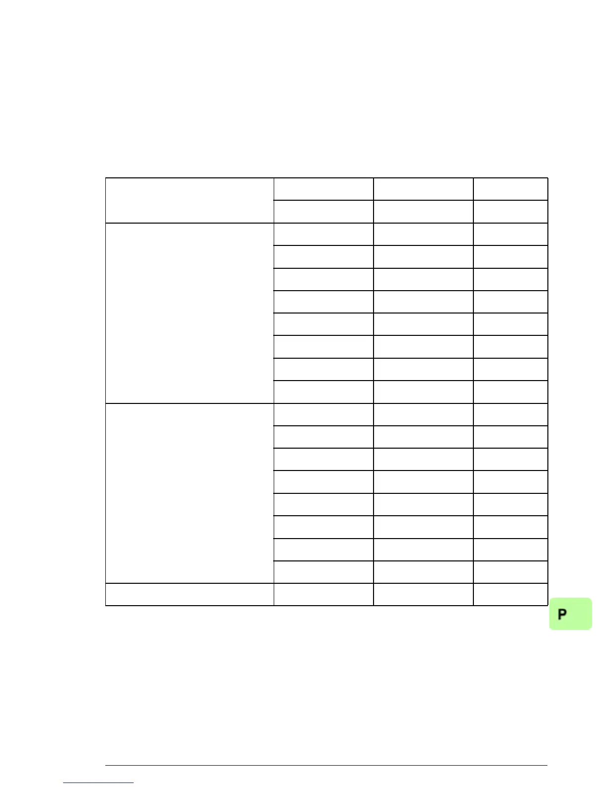
The table below illustrates the structure of a fault buffer. The fault
buffer consists of two parameters: fault number (PNU 947) and
fault code (PNU 945). The rows of the fault buffer are represented
by the parameter subindices. Fault messages are entered into the
buffer in the sequence they are detected. Each line in the fault
buffer represents a fault message, which is a part of a fault
situation. A fault situation lasts from a detection of a fault to its
acknowledgement.
PNU947 PNU945
Fault number Fault code Subindex
Actual fault situation n
0x4210 0x9005 0
001
002
003
004
005
006
007
Fault situation n-1
0x7510 0x900B 8
009
0010
0011
0012
0013
0014
0015
…………
 Loading...