ABB i-bus
®
KNX
Planning and application
FCA/S 1.x.x.1 | 2CDC508134D0202 243
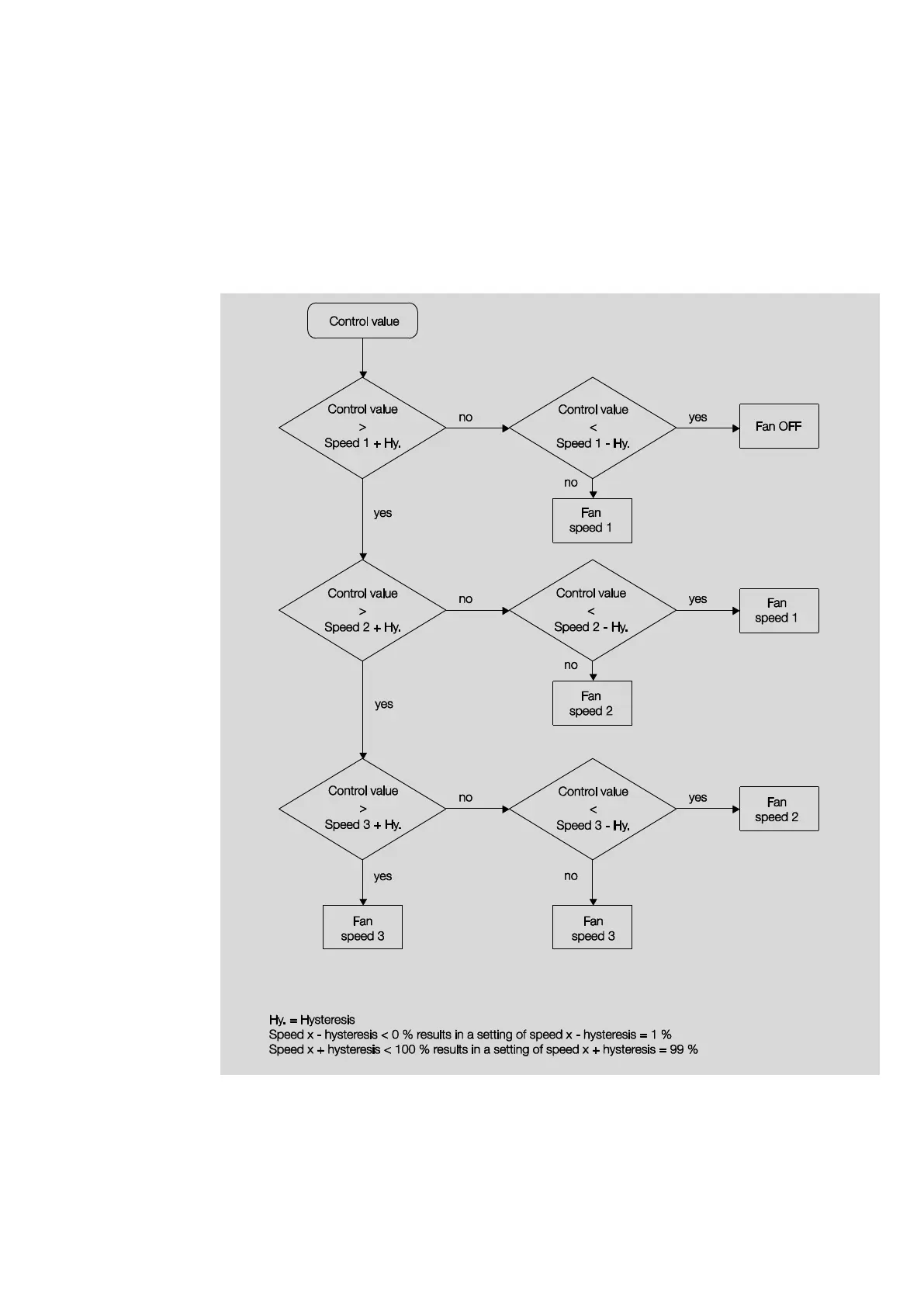
4.1.5 Speed switching logic
The following illustration shows the speed changeover logic for the device depending on the control values
and the parameterized threshold values and hysteresis values.
The diagram relates to a three-speed fan without parameterized fan limitations. The fan limitations are only
relevant after the fan speed has been determined and do not change the flow chart.

 Loading...