Fig. 5.5. Network Connectivity Indicator Lights
5.3.2 Oven controller pcb
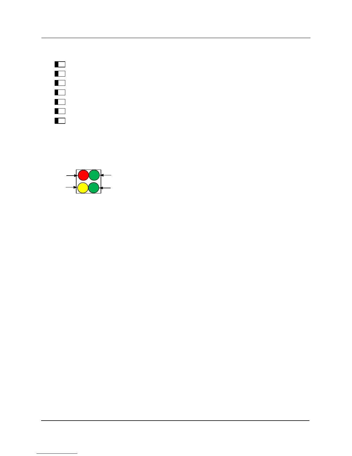
There are four large LEDs at the top, front edge (closest to the front door) of the Oven Controller (OC) PCB, arranged in a 2 by 2
square as shown in Figure 5.6:
Fig. 5.6. Oven Controller PCB Communication Indicators
Upper right: Green – heartbeat that blinks being lit more than off at about once per second
Lower right: Green – blinks whenever a RTC signal is present; blinks faster when a method is active
Lower left: Amber – blinks slowly after power-up while the oven devices are being downloaded code
Upper left: Red – turns on when an error occurs; if heartbeat is blinking, then red indicates a loss of the life indicator
from the master controller; it will turn off if the Master Controller recovers.
Errors during startup will blink the lower left LED with a code that can be counted between pauses:
1 No initialized DPM
2 Unable to create virtual clock
3 Unable to create DPM exception handler
4 Unable to initialize RTC
5 Unable to create tasks
6 CAN comm error (not reliable)
7 Miscellaneous startup error
8 CAN asynchronous receive error
9 RTC asynchronous receive error
10 Error trying to start remote CAN node
11 Error during shutdown
When power is applied to the board, via the system power, the lower pair alternately blink for a few seconds indicating the
bootloader is functioning and loading the oven controller code from the master controller. If the bootloader fails, the two LEDs
will blink in unison five times and stop with an error code:
Off Green Invalid code size
Amber Off No code file
Amber Green No initialized DPM
Six small LEDs on the populated side of the Oven Controller PCB reflect CAN activity. CAN A refers to the oven fiber CANBus;
CAN B refers to the optional electrical CANBus; CAN C refers to the optional fiber CANBus. Under normal operation

 Loading...

