PGC5000
PGC5000 Series Service Instructions 6 Component repair
SI/PGC5000-EN, rev B 38
If equipped with a Wago module, ensure electrical CAN connection is removed from the top of the
controller board before sliding board out.
3. Release board clips at top and bottom.
4. Slide board out.
5. Reverse steps to replace board.
6.2.3 Power supply
Power Supply removal and replacement procedure:
1. Disconnect the wires to the Power Supply and tag them for reconnection.
2. Using a flat blade screwdriver, release the Power Supply from the DIN rail and remove it from the Master Controller.
3. Install the new Power Supply onto the DIN rail.
4. Connect the power input wiring at the bottom of the new Power Supply, to L (line), N (neutral), and earth ground.
5. Connect the output wiring at the top of the new Power Supply (using either set of connections), to the “+” and “-“
connections. Insert one wire in each terminal, when possible. If there is a ground wire, connect it to one of the “-“
connections.
6.2.4 Optional wago modules
Wago module removal and replacement procedure:
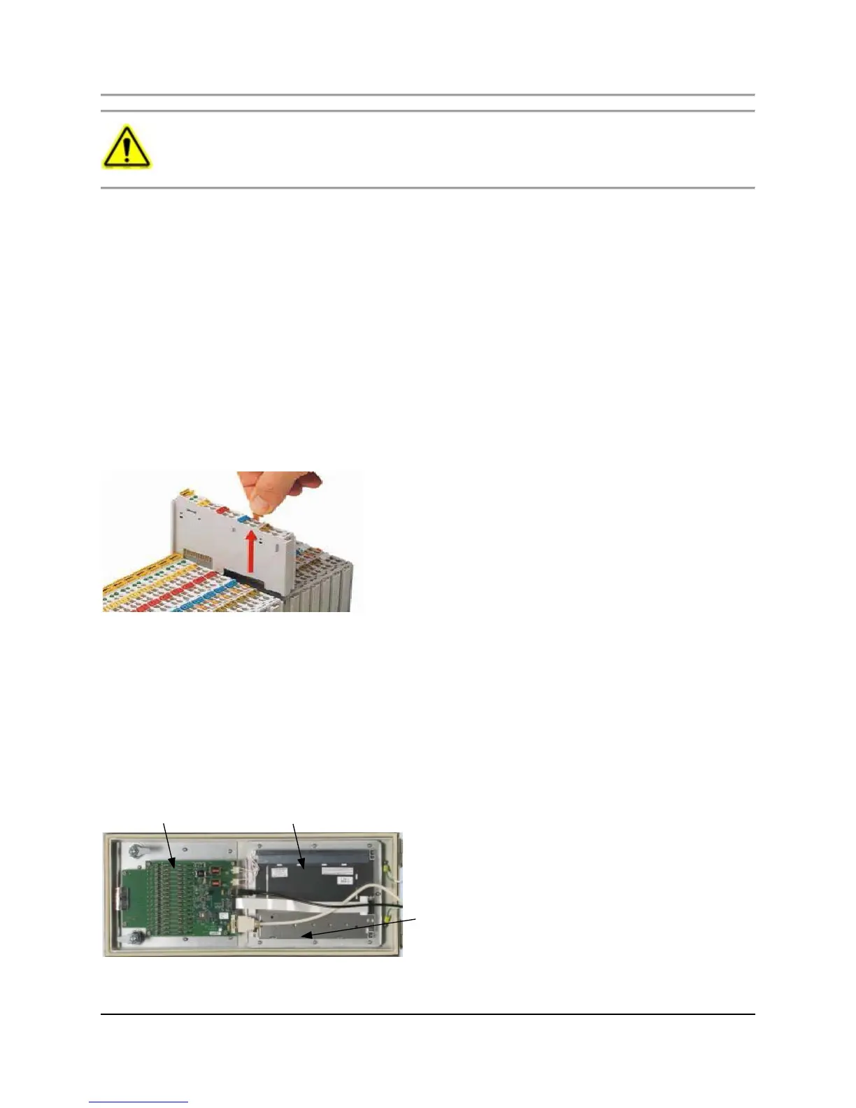
1. On the Wago module assemblies to be replaced, tag all connecting cables (see Figure 6.2)
Fig. 6.2. Removing a Wago Module
2. Disconnect the cables from the modules to be replaced.
3. To release a Wago module from the DIN rail, pull the release tab on the module. The release tab is indicated by the red
arrow shown in Figure 6.2.
4. Install each new Wago module onto the DIN rail, being careful to align the tongue and groove joints on adjacent modules.
5. Reconnect the cables removed in step 2.
6.3 Master controller cabinet door
The back of the Master Controller front door assembly comes complete with the Front Panel PCB, Liquid Crystal Display, Touch
Panel Controller, and associated cables (see Figure 6.3).

 Loading...

