PGC5000
PGC5000 Series Service Instructions 7 Subassembly repair
SI/PGC5000-EN, Rev B 71
3. Turn off power and carrier gas.
4. Open the isothermal oven door.
5. Locate the valve to be replaced.
6. Tag all valve connections.
Service or replacement of the O-rings, plungers, or springs must be performed at the factory. Do not
disassemble the valve unless system malfunction is definitely isolated to the valve. Perform all other
system checks first.
All disassembly operations must be performed in a clean, well-lighted area. Flush all hazardous or toxic
materials from the valve before starting.
7.8.2 Removing a valve
1. With a 1/4-inch wrench, remove the connections from the valve cap.
2. With a 7/64-inch hex key wrench, loosen the clamp ring screw.
3. Remove the valve from the clamp ring and take it out of the analyzer.
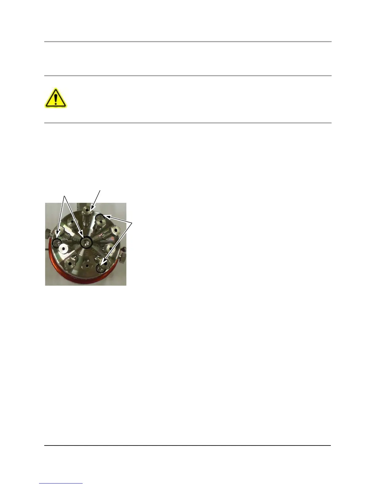
7.8.3 Replacing the diaphragm (four screw type)
1. Remove the three screws around the outside of the valve (see Figure 7.17).
Fig. 7.17. Typical 4 Screw Cap, Showing Port 1 Orientation
2. Remove the center screw.
3. Lift the cap from the two alignment pins.
4. Set the cap aside in a safe, clean place, with the polished side up so that it does not get scratched.
5. With tweezers or a knife blade under the edge of the diaphragm, carefully lift and work the diaphragm off the alignment
pin. Be careful not to tilt the valve, which could let the plungers fall out.
6. Set the valve on a clean surface, with the base down and the plungers up.
7. Put on powder-free gloves.
8 Remove the new diaphragm from its packaging.
9. Hold the diaphragm carefully by the edges so that the surface is not contaminated or damaged.
10. Install the diaphragm in place, making sure the diaphragm groove is aligned with the recess in the cylinder body.
11. Clean the cap thoroughly with an appropriate solvent and a clean tissue or cotton swab, taking care not to damage the
surface.
12. Blow the cap with clean compressed gas to remove any lint left by the tissue or swab.
13. Install the cap over the alignment pins with port number 1 opposite the air inlet (see Figure 7.17).
14. Reinstall the longer screw into the center of the cap.
15. With a torque wrench, tighten this screw to 5 inch-pounds.
16. Reinstall the other three screws around the edges of the cap.
17. With a torque wrench, tighten the center screw to 20 inch-pounds.
18. With a torque wrench, tighten the other three screws to 20 inch-pounds.

 Loading...

