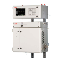
PGC5000
PGC5000 Series Service Instructions Contents
SI/PGC5000-EN, rev B 3
Contents
1 Glossary .............................................................. 5
2 Safety and symbols ............................................. 6
3 Introduction ........................................................ 7
3.1 General ..................................................................... 7
3.2 Drawings .................................................................. 7
3.3 Master controller..................................................... 7
3.4 Class b oven ............................................................. 7
3.4.1 Liquid version.............................................. 8
3.4.2 Vapor version.............................................. 8
3.5 Class c oven .............................................................. 8
3.6 Air purge systems .................................................... 8
3.7 System variations .................................................... 8
4 Maintenance ....................................................... 9
4.1 Equipment and supplies required ........................... 9
4.2 Preventive maintenance ......................................... 9
4.2.1 Gas cylinder replacement .......................... 9
4.2.2 Cleaning .................................................... 10
4.3 System backup ....................................................... 10
4.4 USB connectors...................................................... 10
5 Diagnostics and troubleshooting ....................... 11
5.1 General ................................................................... 11
5.1.1 Power-on self test ................................................. 11
5.1.2 Indicator boxes and hex codes.............................. 11
5.2 Power ..................................................................... 13
5.2.1 Power failure recovery ............................. 13
5.2.2 Oven LED indicators ................................. 13
5.2.3 System board battery ............................... 14
5.3 Board level light emitting diodes .......................... 14
5.3.1 Single board computer ............................. 14
5.3.2 Oven controller pcb .................................. 16
5.3.3 DTC digital pcb, version 1 ......................... 17
5.3.4 DTC digital pcb, version 2 ......................... 19
5.3.5 Detector CANbus node identification...... 20
5.4 Indicator troubleshooting procedures ................. 21
5.4.1 I
dentifying issues ...................................... 21
5.4.2 Correcting issues ...................................... 21
5.5 Status indicators .................................................... 21
5.6 Operation troubleshooting ................................... 27
5.6.1 Baseline noise ........................................... 27
5.6.2 Baseline or signal offset ........................... 27
5.6.3 No peaks ................................................... 28
5.6.4 Double sampling ....................................... 28
5.6.5 Mystery peaks .......................................... 28
5.6.6 Individual peak missing on report ........... 29
5.6.7 Chromatogram oversized or off scale ..... 29
5.6.8 Variable sample size ................................. 29
5.6.9 Variable retention times .......................... 29
5.6.10 Reduced peak size .................................... 29
5.6.11 Loss of power ............................................ 26
5.6.12 Flame Out LED on ..................................... 30
5.7 Software ................................................................. 30
5.7.1 System backup and recovery.................... 30
5.7.2 System backup error messages ................ 31
5.8 Restarting the analyzer .......................................... 32
5.9 Upgrading software ............................................... 33
5.10 Optional discharge ionization detector ................ 33
5.10.1 Plasma will not light .................................. 33
5.10.2 No signal .................................................... 33
5.10.3 Low signal .................................................. 34
5.10.4 Noisy .......................................................... 34
5.10.5 High baseline ............................................. 35
5.10.6 Drifting baseline ........................................ 35
5.10.7 Spikes ......................................................... 35
5.10.8 Shifting retention times ............................ 35
6 Component repair ............................................. 36
6.1 General ................................................................... 36
6.1.1 Preparation and procedures .................... 36
6.1.2 El
ectrostatic discharge information ......... 36
6.1.3 Powering down the analyzer system ....... 36
6.1.4 Equipment and supplies required ............ 36
6.2 Master controller cabinet ...................................... 37
6.2.1 SBC and card cage assembly..................... 37
6.2.2 Oven controller pcb .................................. 38
6.2.3 Power supply ............................................. 38
6.2.4 Optional wago modules ............................ 38
6.3 Master controller cabinet door ............................. 38
6.3.1 Front panel pcb ......................................... 39
6.3.2 Liquid crystal display assembly ................ 39
6.4 Oven component locations ................................... 40
6.4.1 Class b oven components, v1 ................... 40
6.4.2 Class b oven components, v2 ................... 40
6.4.3 Class c oven components ......................... 41
6.5 Replacing the epc control pcb ............................... 41
6.6 Replacing the epc control assy .............................. 41
6.6.1 Preparation ............................................... 41
6.6.2 Removing the epc control assy ................ 42
6.6.3 Installing the epc control assy .................. 43
6.6.4 Removing a sensor pcb ............................. 44
6.6.5 Installing a new sensor pcb ...................... 45
6.6.6 Removing a proportional valve ................ 45
6.6.7 Installing a new proportional valve .......... 46
6.6.8 Removing the control pcb ........................ 46
6.6.9 Installing a new control pcb ..................... 46
6.6.10 Removing the heater ................................ 47
6.6.11 Installing a new heater ............................. 47
6.7 FID amplifier assembly ........................................... 47
6.8 FPD electrometer ................................................... 48
6.9 TCD amplifier assemblly ........................................ 48
6.10 Replacing the dtc analog pcb, v1 ........................... 48
6.11 Replacing optional zone board .............................. 49
6.12 Replacing dtc digital pcb, v1 .................................. 49
6.13 R
eplacing oven indicator pcb ................................ 49
6.14 Replacing dtc master analog pcb, v2..................... 49
6.15 Replacing dtc digital pcb, v2 .................................. 50
6.16 Replacing dtc auxiliary pcb .................................... 50

 Loading...