1MRK 500 124-UEN Section 4
Local HMI
Operation Manual 73
Distributed busbar protection REB500
4.3 Operation
4.3.1 Introduction
Operation in the case of the busbar protection system is confined to supervising the
proper function of the system and assessing the system data.
There are different ways of viewing operating, disturbance and tripping data:
• local HMI
• PC running HMI500
• remote HMI
• station automation system (SCS)
(see Section 2 “System Overview”)
4.3.2 Viewing data on the local HMI
The local HMI provides a quick overview of the status of the protection (normal
operation, alarms and trips) without having to connect a PC.
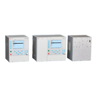
It is fitted in every central unit and as an option in the bay units. On the front, it has
a 320 by 240 pixel display, three protection LEDs, 19 pushbuttons and 15
signalization/alarm LEDs. The local HMI enable the equipment to be operated and
controlled simply and conveniently where it is installed. An interface is also
provided for connecting a PC via RS45
Whether on the central unit or a bay unit, the local HMI enables the following to be
viewed:
• current and voltage measurements
• statuses of inputs and outputs
• alarms (generated by the respective bay unit)
• system (or respective bay unit) settings
• settings of all the specific bay unit protection functions
 Loading...


