101
20. Appendix C: Tripping time indication
The example below indicates explain tripping time indication on REF542plus
HMI. The example refers to the overcurrent instantaneous protection
function.
Setting values in REF542plus are:
Set time = 80 ms
Set threshold = 0,1 In
A051660
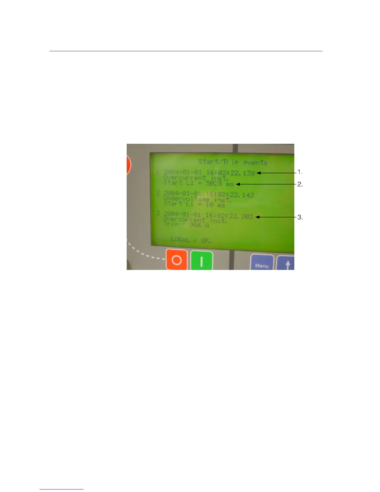
Fig. 20.-1 Start/Trip events
Event nr.1
The protection function enters the start condition, for example the current is
above the set threshold, at 01/01/2004, 16:02:22.138, absolute time. The
arrow 1 indicates the time, see Fig. 20.-1.
Event nr. 3
The set time has elapsed with the current above the set threshold. Therefore,
the trip signal is generated at 01/01/2004, 16:02:22.203, absolute time. The
arrow 3 indicates the time, see Fig. 20.-1.
The set time in REF542plus, 80 ms in this case, must be compared to the time
obtained by the following computation:
(Trip signal time: event nr. 3 time)-(start time: event nr.1 time)+compensation
time(*)
In this specific case assuming a BIO3 module inside the REF542plus:
1MRS755869
Multifunction Protection and Switchgear Control
Unit
Operator's manual
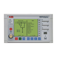
REF542plus

 Loading...