15
3.3. REF542plus status information area
A051338
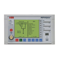
Fig. 3.3.-1 Status Information area
1 Unit status
2 Network Communication status
3 Alarm
4 Interlocking Error
The HMI shows the following status information:
*
Ready. This green LED is turned on when the unit is in the operational
state. The LED is switched off when the auxiliary power is not present or
when the unit is not operational (FUPLA is not running).
*
Network Communication. This LED is meaningful only when the
REF542plus is equipped with a communication module. When a
communication module is detected the LED turns on to green. If the
module is not detected or fails, the LED turns red. When a Modbus
communication module is installed, the LED becomes orange if the
communication error rate increases. It becomes red when the
communication error rate prevents good communication. The LED
comes back to green when no communication errors occur or by
resetting the module status registers (see the Modbus technical reference).
When there is no communication module, the LED is always switched off.
*
Alarm: this LED turns to red when the user defined alarms become
true. Several arbitrary alarm conditions can be defined and configured
with the Operating Tool. Alarm conditions could be the trip of a
protection function, loss of SF6 in the circuit breaker and so on. When
this LED is on, it is not possible to close the circuit breaker or to
download a new configuration. The alarm must be acknowledged first.
*
Interlocking Error: this LED is usually green. It turns temporarily to
red when the user attempts an operation that would violate the
programmed interlocking con ditions; for example switchi ng a
disconnector with the circuit breaker in closed position.
1MRS755869
Multifunction Protection and Switchgear Control
Unit
Operator's manual
REF542plus

 Loading...