13.7. Optical output commissioning page.... .......................... .... 47
14. Connection to PC.... ......................................................... 49
14.1. Optical to RS232 converter cable.... ............................. .... 49
14.2. Downloading a configuration.... ..................................... .... 49
14.2.1. Serial port settings.... ................................ ...... .... 50
14.3. Uploading the configuration.... ....................................... .... 52
14.4. Uploading other information........................................... .... 53
15. Troubleshooting................................................................ 55
15.1. Error messages.............................................................. .... 55
15.2. Clearing the configuration inside the unit...................... .... 60
15.3. Primary objects incorrect visualization.... ...................... .... 60
16. Terminology.... ................................................................... 63
17. Abbreviations.... ................................................................ 65
18. Appendix A: Connection diagrams................................ 67
18.1. Analog Inputs.... ............................................................. .... 69
18.2. Binary inputs and outputs.... .......................................... .... 72
18.2.1. Static.... ............................................................ .... 72
18.2.2. Electromechanical.... ....................................... .... 73
18.2.2.1. BIO3.... ............................................ .... 73
18.3. Other connections.... ...................................................... .... 75
18.3.1. Analog outputs 0/4-20 mA.... .......................... .... 75
18.3.2. Analog inputs 4-20 mA.... ............................... .... 75
18.3.3. Communication module................................... .... 76
18.3.4. Power supply.... ............................................... .... 76
18.3.5. Time synchronization.... .................................. .... 77
18.3.6. HMI.... .............................................................. .... 77
19. Appendix B: Menu structure........................................... 79
19.1. Reset page.... .................................. ............................... .... 80
19.2. Service page.... .............................................................. .... 82
19.3. Test page........................................................................ .... 98
19.3.1. Test HMI........................................................... .... 98
19.3.2. Test primary object.... ...................................... .... 99
20. Appendix C: Tripping time indication.......................... 101
4
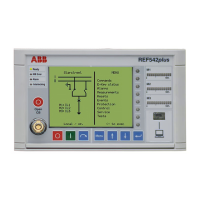
REF542plus
Multifunction Protection and Switchgear Control
Unit
Operator's manual
1MRS755869

 Loading...