Section 3 1MDU07212-YN Rev. C
Technical Data
16 REF601 / REJ601
Application Manual
Section 3 Technical Data
For detailed technical data please refer the product guide.
Section 4 Protection and Control Function
4.1 Three Phase Overcurrent Protection
4.1.1 Functionality
The three-phase overcurrent protections can be used as three phase non-directional
overcurrent and short-circuit protection for feeders.
The operate time characteristics for low stage can be selected to be either definite
time (DT) or inverse definite minimum time (IDMT). The high and instantaneous
stage always operates with the definite time (DT) characteristics.
4.1.2 Principle of Operation
The three-phase overcurrent unit continuously measures all three phase currents of
the protected object. The maximum current of the three phases is evaluated by the
low stage (I> / 51), high stage (I>> / 50-1) and instantaneous stage (I>>> / 50-2) of
phase overcurrent functions.
On occurrence of fault, fulfilling the trip condition of respective stage, the LED
“Trip” and “Trip Ip” will be activated as configured. Additional the output relays
(Trip and signalization) will be activated according the binary output configuration.
Each of the stages could be blocked by settings or via binary input of the relay.
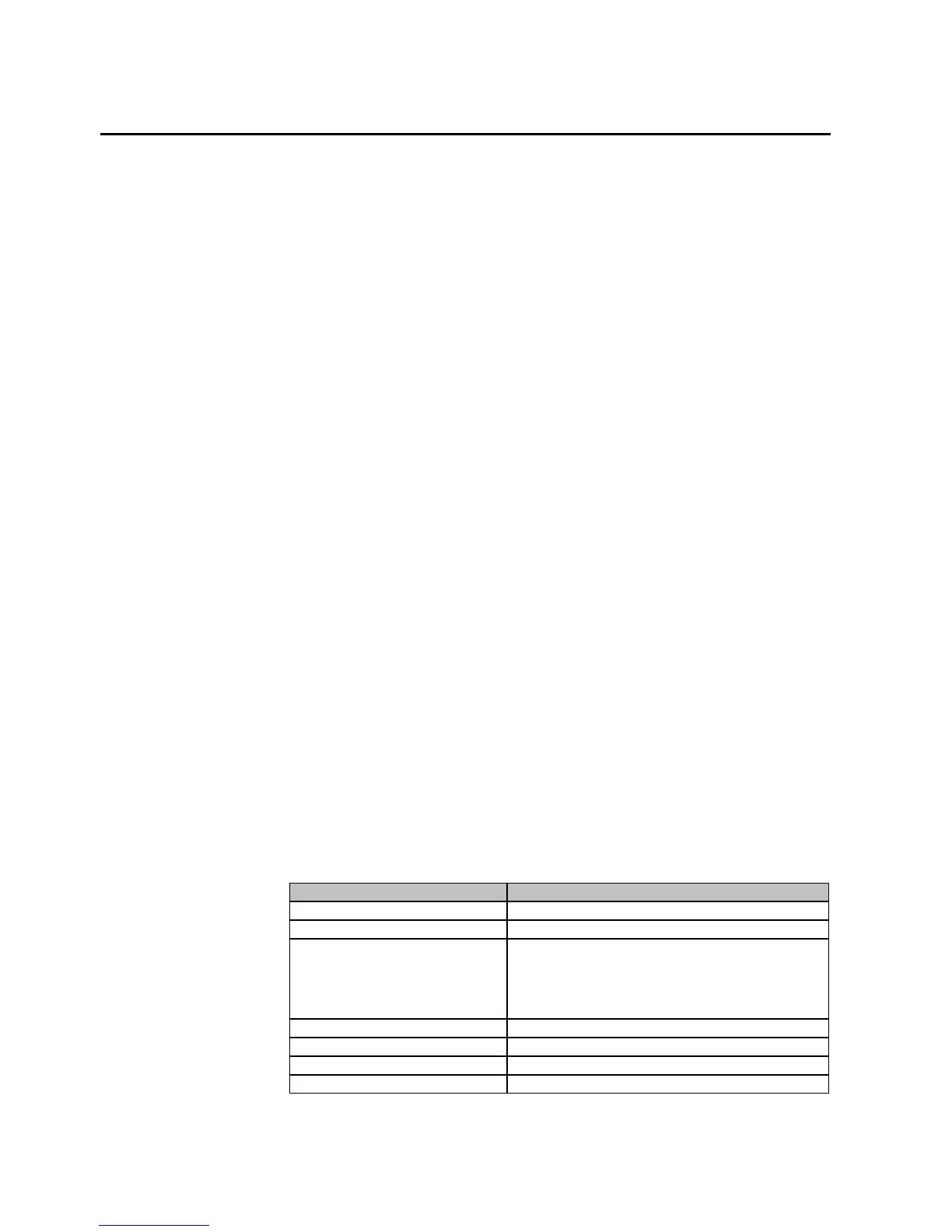
4.1.3 Setting range of Three Phase Overcurrent Protection
Table 4: Setting ranges Non-directional overcurrent protection, Low stage 3I>, 51
Description Value
Setting range of pick-up current I > 0.1...2.50 x In in steps 0.001, infinite
Operate time delay (DT) t > 0.04...64 sec in steps of 0.01
Operating curve type (IDMT)
IEC 60255-3: Normal inverse, Very inverse, Extremely
inverse, Long-time inverse
ANSI C37.112: Moderate inverse, Normal Inverse, Very
inverse, Extremely inverse
Special curves: RI inverse
Time multiplier setting k (IDMT) 0.02...1.6, in steps of 0.01
Reset ratio IDMT : 0.96 and DT : 0.98
Reset time 40 msec
Trig CBFP Yes / No

 Loading...


