Section 4 1MDU07212-YN Rev. C
Protection and Control Function
34 REF601 / REJ601
Application Manual
· External close command available at binary input (configured for Breaker
command operation) as well command available from MODBUS / IEC_103 or
Front HMI
· External user defined Signal 1 to Signal 3 available at binary input (configured
via binary input menu)
Apart from above signals, the UNIT READY status is fixed configured at BO4 and
cannot be changed. No other signals can be configured at BO4.
Table 21: Trip and signaling contacts
Binary output Default configuration
Default as Trip1 contact for O/C and E/F. Under relay healthy condition, this
contact will remain open. In the event of trip/breaker open command, it will
Default as Trip2 contact for breaker open output. In the event of fault (O/C
and E/F) / breaker open command, it will close
Default as contact for Breaker close command. This contact will close, when
breaker close command is received either from relay HMI or through
configurable signaling contact for Unit ready / internal relay fault
indication. Under relay healthy condition this will be in close condition. During
Default as signaling contact over current trip. In the event of phase faults (I>,
I>> and I >>>) it will close
Default as signaling contact earth fault trip. In the event of earth faults (Io>
4.12 Configurable LED
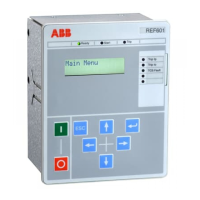
The relay has total five LED’s for user defined signaling. The can be configured
with the same signals as the binary output contacts. They can be individually
configured for following different operating modes:
1. Self-reset mode (S): In self-reset mode, the binary output follows the behavior
of the triggering signal. The output remains in active state till trigger persists.
2. Hold mode (H): Once output is activated, it will remain active even if trigger
signal drops.
Output can be reset by all possible reset input triggers
a local HMI by reset key combination
b Reset binary input
c Reset command from optional communication module via MODBUS
/ IEC.
All five user defined LED’s can be triggered by different protection and control
signals. It is possible to map same signal to trigger more than one binary output.
The signals available for triggering binary outputs are as follows:
· Individual start of protection functions I>, I>>, I>>>, Io> and Io>>
· Individual trip of protection functions I>, I>>, I>>>, Io> and Io>>
· External user defined Signal 1 to Signal 3 available at binary input (configured
via binary input menu)

 Loading...