1MDU07212-YN Rev. C Section 4
Protection and Control Function
REF601 / REJ601 21
Application Manual
4.6.2 Principle of Operation
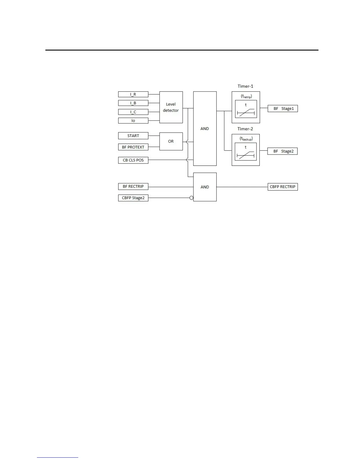
The operation of the breaker failure protection can be described using a module
diagram.
Figure 3: Circuit breaker failure protection functional module diagram
The measured phase currents are compared phasewise to the set I
CBFP
. Similarly the
neutral current is compared to the set I
oCBFP
. If either of these measured values
exceeds the respective setting, the level detector gives permissive to CBFP
initiation logic.
The CBFP initiation logic is triggered by the rising edge of the START (from
protection function I>, I>>, I>>>, Io> and Io>>) input or by the rising edge of the
BF PROTEXT input wired to digital input of relay as external protection trip.
Retrip function
On receipt of trigger signal and reporting of exceeding value of the current by level
detector, the CBFP initiation logic activates Timer 1. In case if relay is configured
to received CB closed position information at any binary input that information is
also used in deciding activation of Timer 1.
Once activated, the timer runs until the set t
retrip
value has elapsed. The time
characteristic for retrip function is according to definite time. When the operation
timer has reached the maximum time value, the BF STAGE1 output is activated.

 Loading...


