Section 5 1MDU07212-YN Rev. C
Use of LHMI
38 REF601 / REJ601
Application Manual
Section 5 Use of LHMI
5.1 Overview
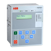
Figure 10: Local HMI of relay REF601/REJ601
The local HMI of the relay contains following elements:
· LED indicators
· LCD display
· Navigation buttons / keys
The LHMI is used for setting, monitoring and controlling.
5.1.1 LED’s
LED’s displays following information respective status
Ready: Green LED
Start: Yellow LED lights after any start of a protection function
Trip: Red LED lights after any trip of protection function
LED 1…5 Red LED functionality as configured
5.1.2 LCD display
The LHMI includes 2 x 16 character LCD display respective 2 line of Chinese
characters. The measurement, recorded data, events, settings etc. can be viewed in
the display.
5.1.3 Navigation
The LHMI keypad consists of push buttons which are used to navigate in different
views or menus. With control push buttons the open or close commands can be
given to breaker. The push buttons are also used to acknowledge alarms, reset
indications and reset of lockout functions.
Table 26: LHMI push buttons
Key Picture Key Name Description
Up
Used for incrementing of parameter value while editing, or
provides up level selection of menu item.
Down
Used for decrementing of parameter value while editing, or
provides down level selection of menu item.

 Loading...