1MDU07212-YN Rev. C Section 4
Protection and Control Function
REF601 / REJ601 37
Application Manual
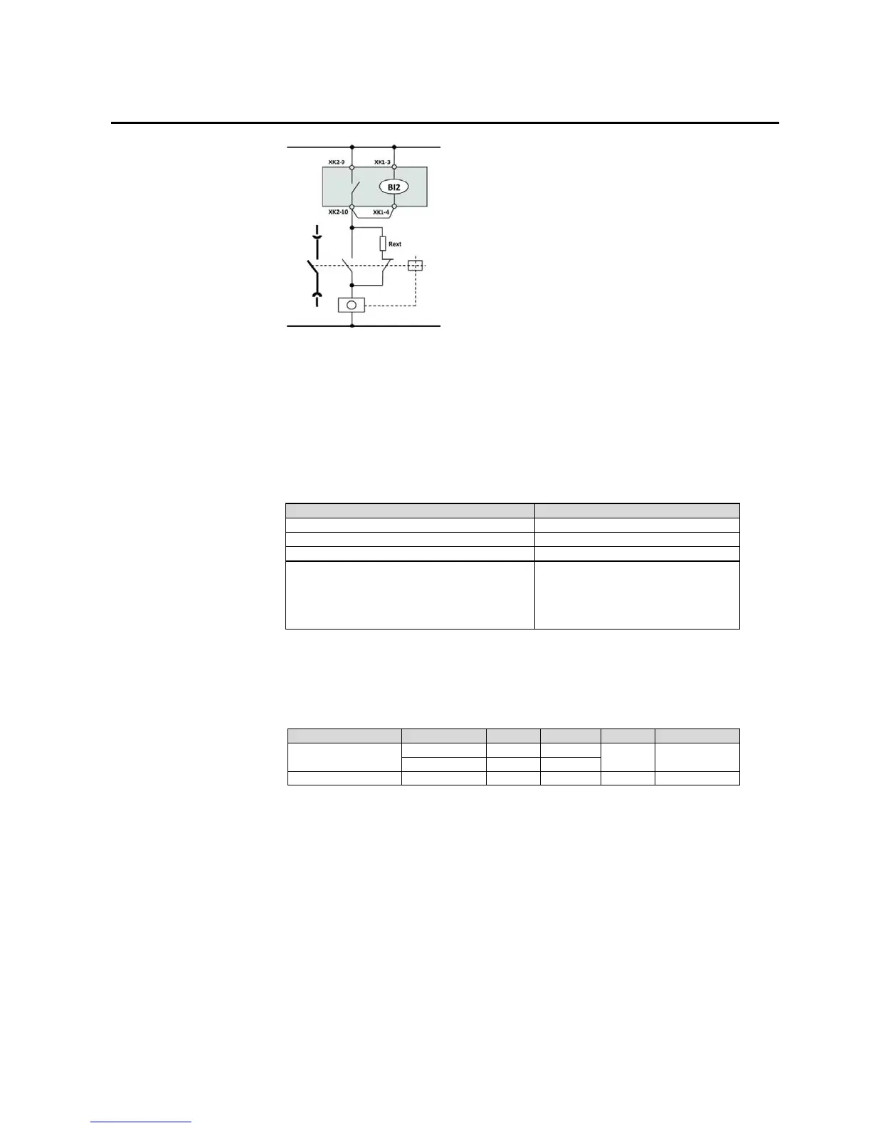
Figure 8: Application diagram of TCS function
When the circuit breaker is open, TCS measure the voltage across the trip contact
through Rext (external shunt resistance shown in below figure) and trip coil. When
the circuit breaker is close, TCS measure the voltage across the trip contact through
CB internal contact and trip coil. Below table shows the specification for the Rext
for the TCS circuit.
Table 24: TCS functionality specification
Current drain through the supervision circuit
Minimum voltage over the TCS contact
48 V DC
60 V DC
110 V DC
Recommended shunt resistor R
1.2 kΩ, 5 W
5.6 kΩ, 5 W
22 kΩ, 5 W
Whenever TCS functionality is enabled, it is recommended to connect R
ext
.
Otherwise, TCS sees a faulty trip circuit in open circuit breaker position.
Table 25: TCS functionality parameters and selection range
Operate delay time
1 Settable

 Loading...


