Section 4 1MDU07212-YN Rev. C
Protection and Control Function
30 REF601 / REJ601
Application Manual
4.9.2.1 Setting range for thermal overload protection
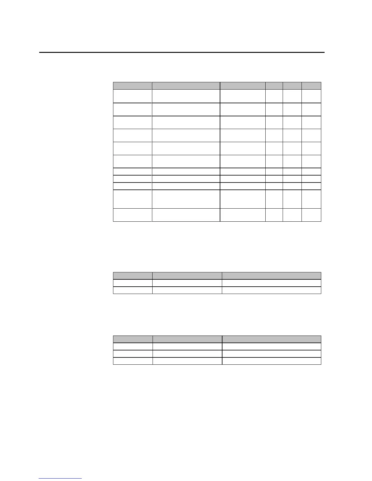
Table 16 Setting range for thermal overload protection 3Ith, 49
Parameter Description Range Unit Step Default
Mode ϑ
Mode of thermal overload
protection*
0 = rotating
1 = static
- 1 0
ϑ
0
Initial thermal level of the
apparatus
0…100 % 1 80
I
b
Reference current leading to
thermal calculation
0.1 … 1.5 xIn 0.1 1.0
τ
↑
Heating time constant of
machine
1 … 300 min 1 45
τ
↓s
Cooling time constant of static
machine
1 … 300 min 1 45
τ
↓r
Cooling time constant of
rotating machine*
1 … 1000 min 1 180
ϑ
alm
Alarm value 50 … 200 % 1 121
ϑ
trip
Operate value 50 … 200 % 1 144
ϑ
startinhibit
Start inhibit value 50 … 200 % 1 105
ϑ
EM
Percentage by which
trip
will be increased in emergency
mode
10… 100 % 1 50
Mode ϑ
powerOFF
Options for calculating thermal
value during power interruption
1…4 - 1 4
*Setting in REF601 and REJ601 hidden (fixed set to static mode)
4.9.2.2 Configurable inputs to thermal overload protection
Table 17 Configurable inputs to thermal overload protection 3Ith, 49
Name Type Description
RESET BOOL
BLOCK BOOL
4.9.2.3 Configurable outputs of thermal overload protection
Table 18 Configurable inputs to thermal overload protection 3Ith, 49
Name Type Description
ALARM BOOL Alarm
OPERATE BOOL Operate
Θ REAL Value of thermal image

 Loading...


