WaterMaster
Electromagnetic flowmeter 4 Electrical Installation
18 IM/WM–EN Rev. M
4.3 Transmitter Terminal Connections
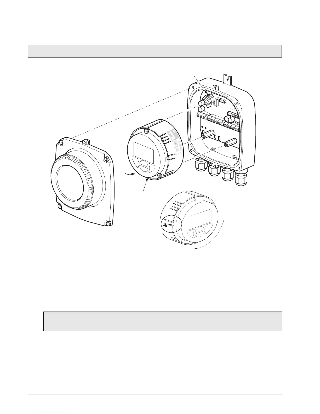
Referring to Fig. 4.8:
1. Slacken (but do not remove) the four transmitter cover screws
A.
2. Remove the transmitter cover.
3. Check that the power indicator LED
B on the backplane is not lit.
4. If screws
C are not visible, access them by gently pulling the rotation lock D back and rotating the
cartridge
E until the cartridge screw access holes align with the cartridge screw heads.
5. Slacken the three cartridge screws and lift the cartridge
F away from the housing.
Warning. Isolate the transmitter from power supplies before removing the cover.
Fig. 4.8 Accessing the Transmitter Terminals
Warning. If the power indicator LED B is lit, the transmitter is still powered up. Before
continuing, isolate the transmitter power supply.
 Loading...


