WaterMaster
Electromagnetic flowmeter 4 Electrical Installation
IM/WM–EN Rev. M 21
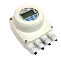
4.5.1 Sensor Cable Terminal Connections and Recommended Cable Lengths
Fig. 4.10 Sensor Cable Connections at Transmitter Terminal Block – Standard System
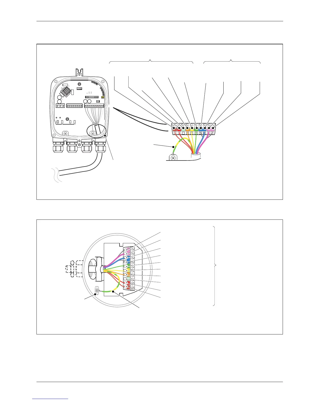
Fig. 4.11 Sensor Cable Connections at Sensor Terminal Block – Standard System
Refer to Section 4.4, page 20 for cable
preparation requirements before connecting
cable
**Drain Wire
(Twisted with
Screen from
D1/TFE – Orange
and D2 – Yellow)
**For Cathodically Protected Systems (or if the transmitter enclosure does not have an earth screw)
connect the drain wire to terminal SCR.
M1
Brown
M2
Red
SCR
Screen
D1/TFE
Orange
D2
Yellow
3
Green
(Sleeve)
S2
Blue
(Screen)
S1
Violet
(Screen)
E2
Blue
(*Signal)
E1
Violet
(*Signal)
Cut cables to 70 mm (2.75 in)
Cut cables to 60 mm (2.35 in)
*Inner Wire
Screen to
Internal Earth
**For Cathodically Protected Systems connect the drain wire to terminal SCR.
**Drain Wire (Twisted with Screen Wire
from D1/TFE – Orange and D2 – Yellow)
S1 Violet (Screen)
Cut cables to
60 mm (2.35 in)
E1 Violet (*Signal)
E2 Blue (*Signal)
S2 Blue (Screen)
3 Green (Sleeve)
D2 Yellow
D1/TFE Orange
SCR (Screen)
M2 Red
M1 Brown
*Inner Wire
 Loading...


