 Loading...
Do you have a question about the ABB WaterMaster and is the answer not in the manual?
| Measurement Principle | Electromagnetic |
|---|---|
| Protection Class | IP67, IP68 |
| Output Signals | 4-20 mA, Pulse, Frequency |
| Liner Material | PTFE, Polyurethane, Hard Rubber |
| Electrode Material | Stainless Steel, Hastelloy, Titanium, Platinum |
| Communication Protocols | HART, Modbus, Profibus |
| Power Supply | 100-240 V AC, 24 V DC |
| Process Connection | Flanged, Wafer |
| Fluid Temperature | -40°C to +180°C (depending on liner material) |
| Process Pressure | Up to 40 bar |
| Conductivity | ≥5 μS/cm |
| Operating Temperature | -20°C to +60°C |
Safety requirements for electrical equipment.
Symbols appearing on equipment labelling.
Health and safety precautions for product use.
Information about the UKAS Calibration Laboratory No. 0255.
Procedures and precautions for unpacking the equipment.
Conditions to consider during installation, including pressure and vibration.
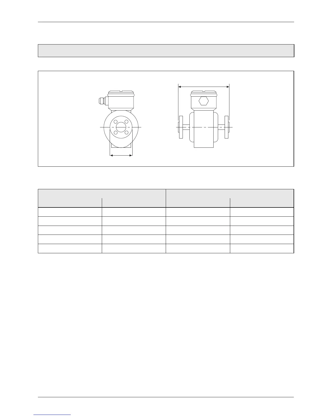
Detailed dimensions for transmitters and sensors.
Dimensions of integral and remote transmitters.
Dimensions for DN10 to DN32 full bore sensors.
Procedures for bonding and grounding the flowmeter and pipelines.
Configuration of remote transmitter and sensor placement.
Steps to access and connect terminals within the transmitter.
Preparing cables for connection to transmitter and sensor.
Guidelines for connecting transmitter and sensor cables.
Wiring details and cable length recommendations for sensor connections.
Procedures for potting sensor terminal boxes to prevent moisture ingress.
Information on connecting output signals.
Wiring diagram for frequency output connections.
Wiring diagram for alarm output connections.
Wiring diagram for 4-20mA current output.
Communication specifications for PROFIBUS and MODBUS variants.
Location and use of test points on the transmitter PCB.
General warnings and requirements for power supply connection.
Wiring diagram and fuse details for AC power supply.
Wiring diagram and fuse details for DC power supply.
Description and function of DIP switches for configuration.
Steps and precautions for refitting the transmitter cartridge and cover.
Explanation of display keys and menu navigation.
Description of common start-up screens and their meanings.
Normal operation screen and accessing menus.
Explanation of user access levels and password protection.
Default passwords for standard and advanced access levels.
Procedure for entering passwords to access menus.
Quick setup procedure for standard and advanced users.
Performance data table for flow rates in m³/h.
Performance data table for flow rates in gal/min.
Pressure limits for sensor operation.
Ambient and process temperature limits for the sensor.
IP ratings for sensor environmental protection.
Minimum conductivity requirement for sensor operation.
Details on electrical connection types for the sensor.
Materials for wetted parts and potable water approvals.
Materials used for electrodes.
Recommended upstream and downstream installation conditions.
Pressure loss specifications at different flow rates.
Materials for non-wetted parts.
Materials for flanges used in sensor construction.
Materials used for the sensor housing.
Specifications for mains, low voltage, and DC power supply.
Rating and configuration of digital outputs.
Specifications for the 4-20mA HART current output.
Accuracy specifications and temperature coefficient.
Communication specifications for PROFIBUS variant.
Communication specifications for MODBUS variant.
Security features to prevent unauthorized access.
Ambient temperature limits for the transmitter.
Information on the infrared service port and compatible adapters.
Material used for the transmitter housing.
Hazardous area approvals for HART variants.
Information on CE, PED, OIML R49, and MID certifications.


