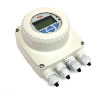
WaterMaster
Electromagnetic flowmeter
IM/WM–EN Rev. M 1
1 Safety ............................................................................................................................................... 2
1.1 Electrical Safety ............................................................................................................................................. 2
1.2 Symbols ........................................................................................................................................................ 2
1.3 Health & Safety ............................................................................................................................................. 3
2 Introduction ...................................................................................................................................... 4
2.1 Quality Control .............................................................................................................................................. 4
3 Mechanical Installation .................................................................................................................... 5
3.1 Unpacking .................................................................................................................................................... 5
3.2 Installation Conditions ................................................................................................................................... 5
3.3 Dimensions ................................................................................................................................................. 10
3.3.1 Transmitter Dimensions ................................................................................................................ 10
3.3.2 Sensor Dimensions ....................................................................................................................... 11
4 Electrical Installation ..................................................................................................................... 15
4.1 Grounding ................................................................................................................................................... 15
4.2 Remote Transmitter / Sensor Arrangement ................................................................................................. 17
4.3 Transmitter Terminal Connections ............................................................................................................... 18
4.4 Cable Preparation (Remote Systems Only) .................................................................................................. 20
4.5 Transmitter / Sensor Cable Connections ..................................................................................................... 20
4.5.1 Sensor Cable Terminal Connections and Recommended Cable Lengths ...................................... 21
4.5.2 Environmental Protection .............................................................................................................. 22
4.6 Output Connections .................................................................................................................................... 23
4.6.1 Frequency Outputs ....................................................................................................................... 23
4.6.2 Alarm Outputs .............................................................................................................................. 24
4.6.3 Current Output (4 to 20 mA) – HART (FEX100) Variant .................................................................. 24
4.6.4 RS485 Communications – PROFIBUS (FEX100–DP) and MODBUS (FEX100–MB) Variants .......... 25
4.6.5 Test Point Access ......................................................................................................................... 25
4.7 Power Supply Connections ......................................................................................................................... 26
4.7.1 AC Power Supply ......................................................................................................................... 26
4.7.2 DC (and Low Voltage AC) Power Supply ......................................................................................27
4.7.3 Configuration DIP Switches .......................................................................................................... 28
4.8 Refitting the Cartridge and Cover ................................................................................................................ 28
5 Start-up and Operation ................................................................................................................. 30
5.1 Navigating the Menus and Parameters ........................................................................................................ 30
5.2 Start-up Screens ......................................................................................................................................... 31
5.3 Security Levels and Password Access ........................................................................................................ 33
5.3.1 Default Passwords ....................................................................................................................... 34
5.3.2 Entering Passwords ...................................................................................................................... 34
5.4 Easy Setup ................................................................................................................................................. 35
6 WaterMaster Flow Performance ................................................................................................... 36
6.1 WaterMaster flow performance – m3/h ....................................................................................................... 36
6.2 WaterMaster flow performance – gal/min .................................................................................................... 38
7 Specification – Sensor ................................................................................................................... 39
8 Specification – Transmitter ........................................................................................................... 42
Notes .................................................................................................................................................... 44
 Loading...


