3-16 Machine Maintenance
Removing the WLAN Module 0
1. Perform the “Removing the Base Door” procedure described on page 3-13.
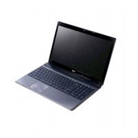
2. Detach the black cable from connector 1 and the white cable from connector 2 on the
WLAN card.
For reference during machine reassembly, note which cable color
corresponds to the main (black) and auxiliary (white) connectors.
Figure 3-16. WLAN Module Antennas
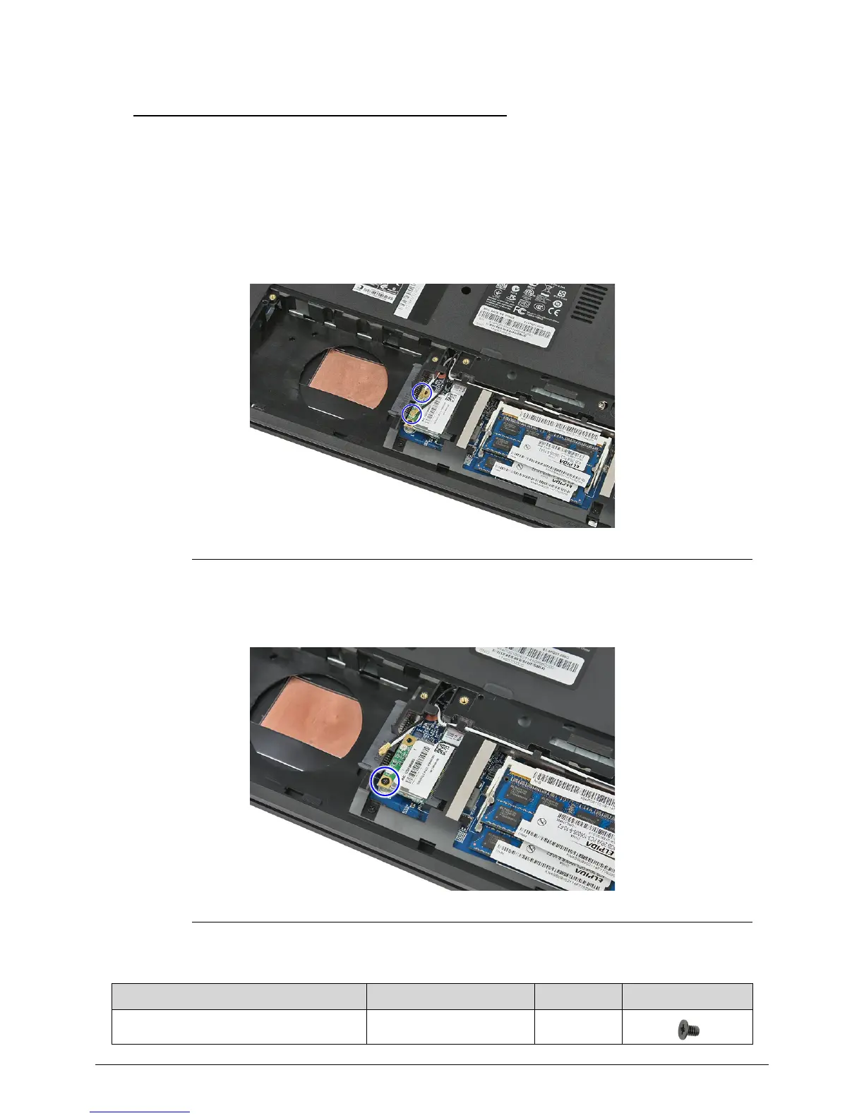
3. Remove the screw securing the WLAN module.
Figure 3-17. WLAN Module Screw
Table 3-8. Screw
Step Screw Quantity Screw Type
WLAN Module Disassembly M2 × L3 1
 Loading...