C
Carrie Carter MDJul 30, 2025
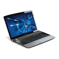
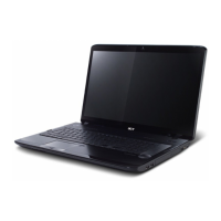
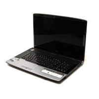
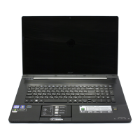
What to do if my Acer Aspire 8930Q Laptop has LCD display problems?
- SShelly McdanielJul 31, 2025
For LCD display problems or other symptoms, consult the “Power-On Self-Test (POST) Error Message”.
 Loading...
What to do if my Acer Aspire 8930Q Laptop has LCD display problems?
For LCD display problems or other symptoms, consult the “Power-On Self-Test (POST) Error Message”.
What to do if POST detects an error on my Acer Aspire 8930Q?
If POST detects an error and displays messages on the screen, refer to the “Error Message List”.
How to fix power failure on Acer Aspire 8930Q?
In case of power failure where the power indicator does not turn on or stay on, refer to the “Power System Check”.
What to do if Acer Aspire 8930Q has intermittent problems?
For symptoms that cannot be recreated, use the customer-reported symptoms and go to “Power-On Self-Test (POST) Error Message” on page 73 “Intermittent Problems” on page 87 “Undetermined Problems” on page 88.
| Screen Size | 18.4 inches |
|---|---|
| Weight | 4.1 kg (9.04 lbs) |
| Screen Resolution | 1920 x 1080 |
| Graphics | NVIDIA GeForce 9700M GT |
| Operating System | Windows Vista Home Premium |
| Optical Drive | Blu-ray Disc drive |
| Networking | Wi-Fi 802.11a/b/g/n, Gigabit Ethernet |
Details on operating system, hardware, display, audio, storage, input/output ports, and environment.
Diagrams illustrating top, bottom, front, left, right, and base views with component identification.
Guidance on Acer utilities like CineDash, Empowering Technology, eAudio, ePower, and eSettings.
Information on touchpad usage, keyboard functions, lock keys, Windows keys, and hotkeys.
Comprehensive specifications for processor, memory, interfaces, drives, and display components.
Introduction and activation of the BIOS setup utility for system configuration.
Explanation of Information, Main, Security, Boot, and Exit menus in BIOS setup.
Procedures for updating BIOS firmware and recovering from BIOS corruption.
Utility to unlock the Hard Disk Drive password.
Tools needed, general precautions, and disassembly sequence flowcharts for the notebook.
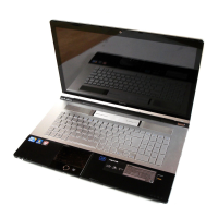
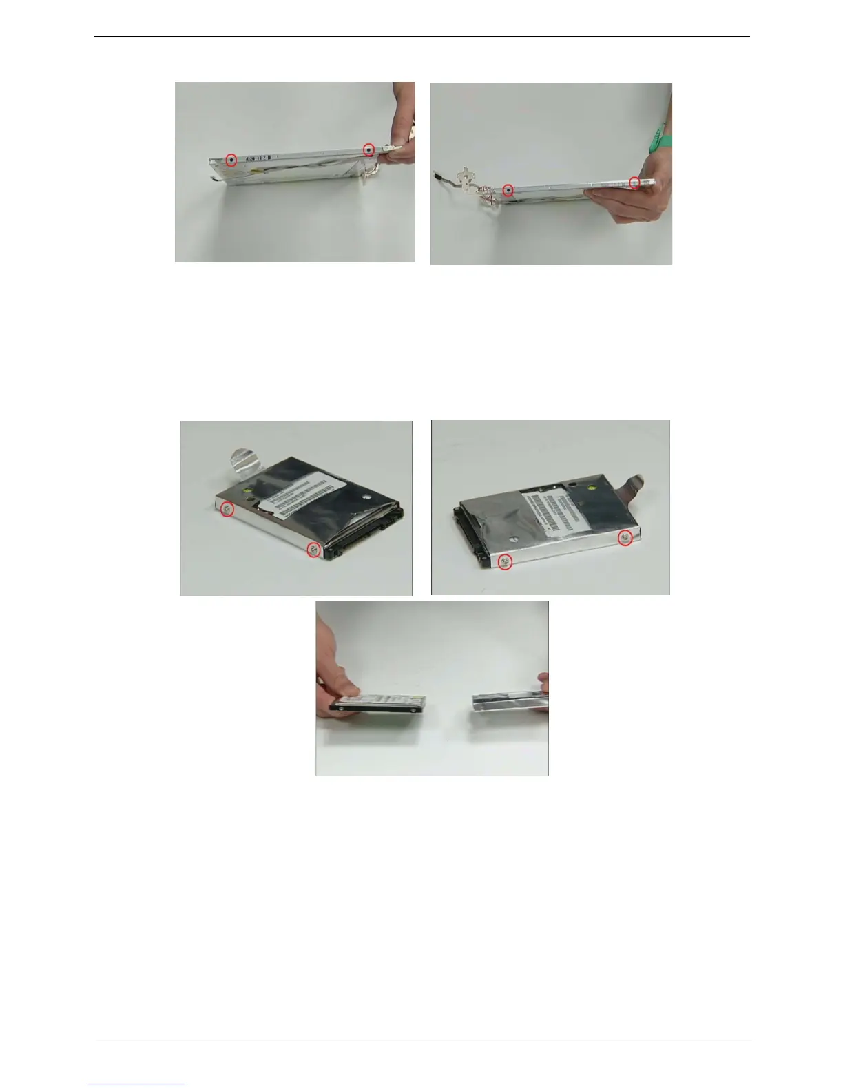
Step-by-step guides for removing battery, HDD, memory, CPU, ODD, and other key parts.
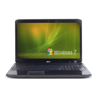
Procedures for disassembling the main unit, I/O boards, and the LCD/LCM module.
Tests for diskette, CD-ROM, keyboard, and input devices to diagnose issues.
Procedures for checking memory modules and power adapter/battery status.
Guidance on interpreting POST error messages and error code lists.
Methods for diagnosing and resolving intermittent and unidentifiable system issues.
Diagrams showing the location of jumpers and connectors on the motherboard (top and bottom views).
List of all Field Replaceable Units with part names and Acer part numbers.
Exploded diagrams and detailed lists of components for various parts like CPU, memory, and cases.