User's Manual | ACOM 1200S | 1.8-54 MHz Linear Power Amplifier
Page
20
of
60
| S e c t i o n INSTALLATION
2.5. Connecting to External Devices (transceiver, computer, etc.) and User Settings
a) CAT/AUX interface connector
Please, see Figure 2-2 Rear panel - Connections, Pos. (1).
CAT/AUX interface is used for connecting and operating with various transceiver models (see Table 2-1
Signals and pin out of the CAT/AUX connector below and the respective menu in Section 5.3 Menu CAT/AUX
SETTINGS (Selection of CAT/AUX Interface), Table 5-1 Transceiver interface type and command set selection and
Figure 5-4 Menu CAT/AUX SETTINGS).
Most of the modern transceivers can be connected by CAT to the ACOM 1200S. This will allow the amplifier
to track the transceiver frequency without any transmission and change the bands automatically when in
OPERATE mode. The cable can be supplied optionally, ordered separately or home brewed according to
Table 2-1 Signals and pin out of the CAT/AUX connector and the transceiver's manual.
The CAT connection requires a cable made especially for the ACOM 1200S and your transceiver. If you need
cable wiring diagrams, please, contact your dealer (see Section 1.2 Owner Assistance).
Note that some of the connections - to the transceiver's BCD band data outputs and
Band Voltage outputs do not provide an exact frequency data, but only band data. Those
connections cannot be used when ACOM 1200S works together with ACOM 04AT
because the tuner needs to know the exact frequency, not only the band.
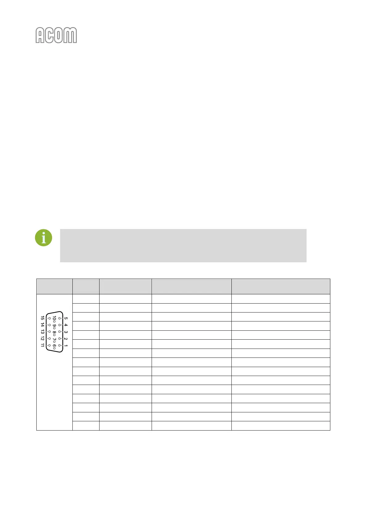
Table 2-1 Signals and pin out of the CAT/AUX connector
D-sub
connector,
15-pin,
3-row,
female
(Rear panel
view)
O.C. output, up to +50 V / 20 mA
Table 2-1 Signals and pin out of the CAT/AUX connector

 Loading...


