EasyManuals Logo

Acom 1200S User Manual

Acom 1200S
60 pages
To Next Page IconTo Next Page
To Previous Page IconTo Previous Page
Page #21 background imageLoading...
Page #21 background image
User's Manual | ACOM 1200S | 1.8-54 MHz Linear Power Amplifier
August 2021
S e c t i o n INSTALLATION | Page
21
of
60
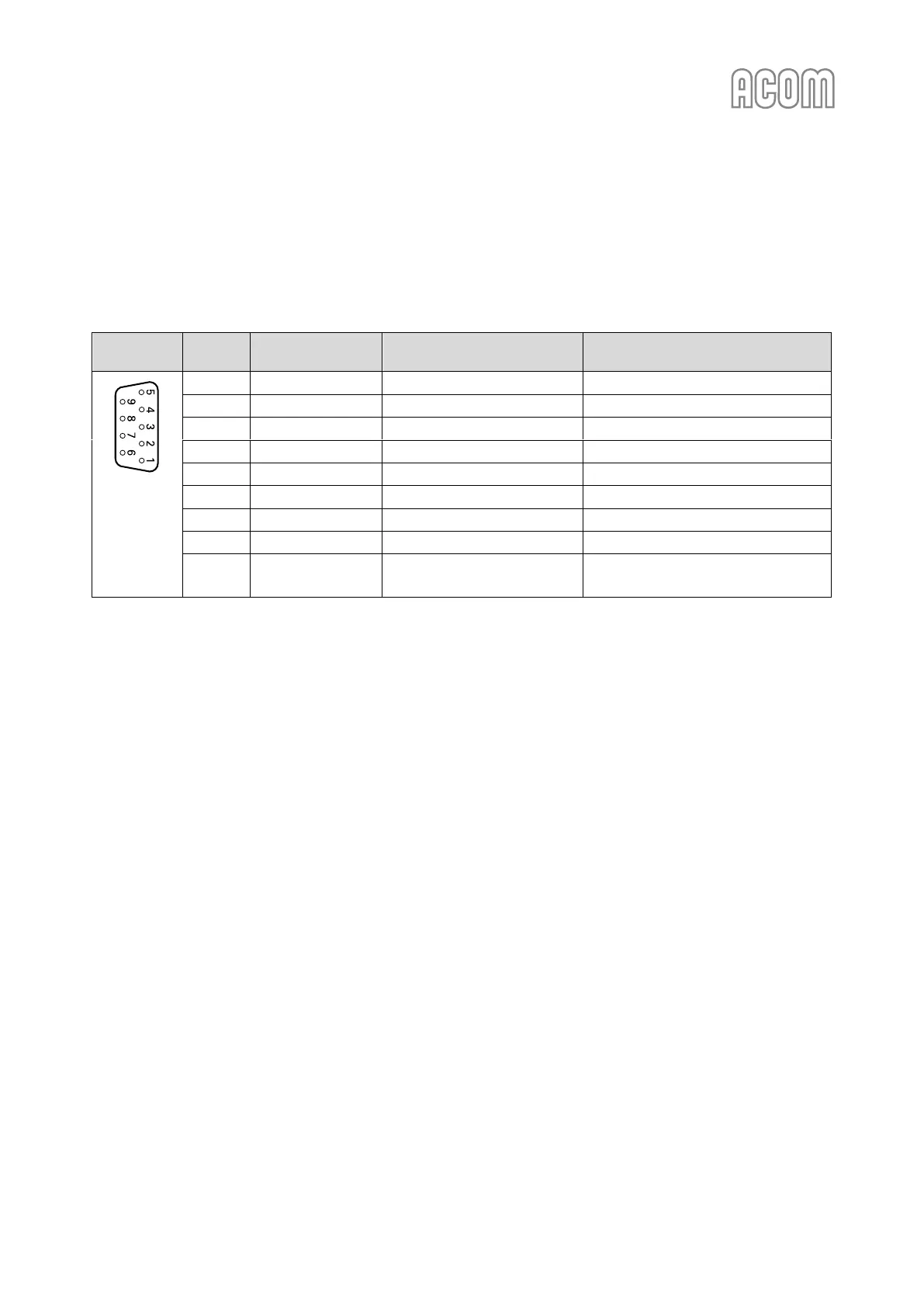
b) RS-232 interface connector
Please, see Figure 2-2 Rear panel - Connections, Pos. (2).
This connector may remain unused until you decide to control the amplifier remotely.
Please, see Section 6.1 Remote Control via ACOM eBox.
Table 2-2 Signals and pin out of the RS-232 connector
RS-232
interface
Pin Nr.
Pin name
Description
Specification
D-sub
connector,
9-pin,
female
(Rear panel
view)
1
-
Not connected
-
2
TxD
Transmit Data
RS-232 level output
3
RxD
Receive Data
RS-232 level input
4
-
Not connected
-
5
GND
Ground
0 Volt
6
DSR
Remote Power On
RS-232 level input
7
-
Not connected
-
8
CTS
Remote Power On
RS-232 level input
9
-
Not connected
-
Table 2-2 Signals and pin out of the RS-232 connector

Table of Contents

Other manuals for Acom 1200S

Questions and Answers:

Question and Answer IconNeed help?

Do you have a question about the Acom 1200S and is the answer not in the manual?

Acom 1200S Specifications

General IconGeneral
BrandAcom
Model1200S
CategoryAmplifier
LanguageEnglish

Related product manuals