User's Manual | ACOM 1200S | 1.8-54 MHz Linear Power Amplifier
S e c t i o n OPERATION | Page
33
of
60
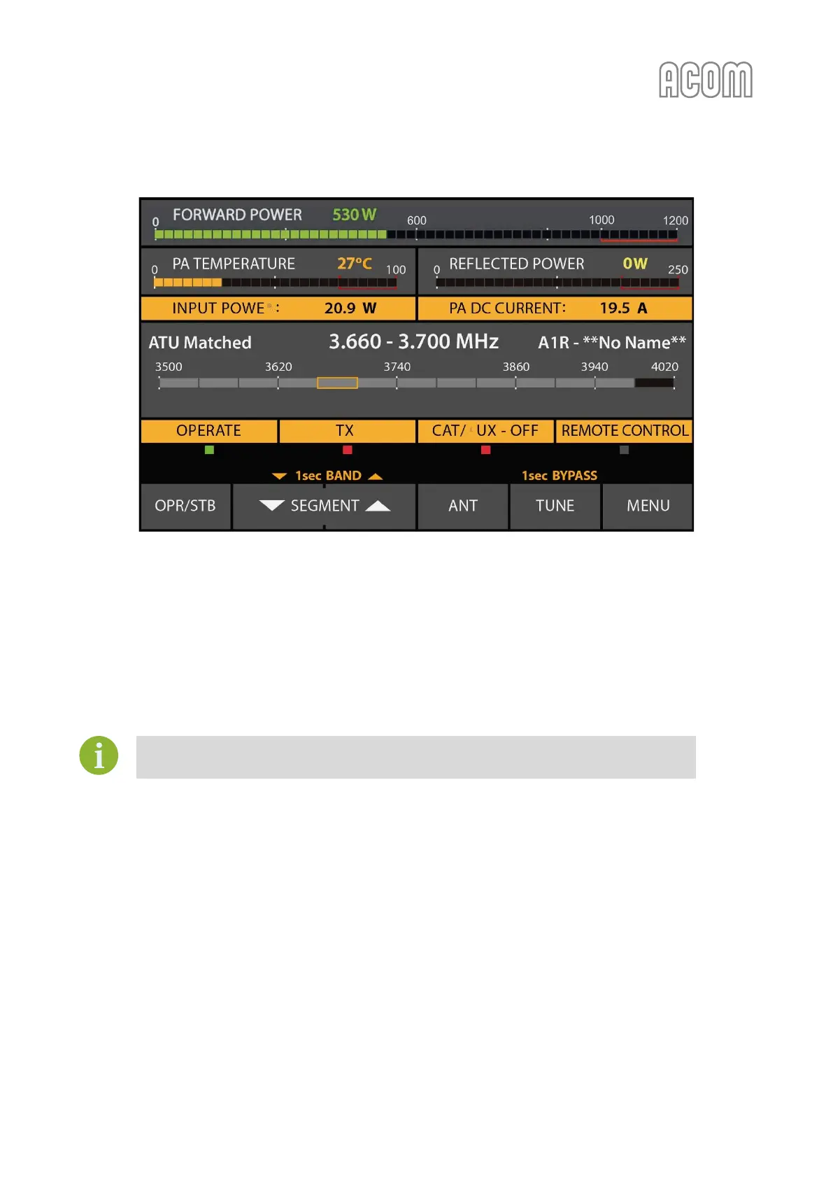
Figure 4-2 Amplifier screen with ACOM 04AT antenna tuner installed
Figure 4-2 Amplifier screen with ACOM 04AT antenna tuner installed
The operation of ACOM 1200S with ACOM 04AT is described in detail in the ACOM 04AT User's Manual
(available for download at www.acom-bg.com).
Pay particular attention to Sections 3.2 Indications, controls and menus, and 4.2 Tuner Assignment and
Unassignment in the downloaded manual for details on ACOM 04AT control from amplifier front panel.
Use of other antenna tuners is not recommended.
4.4. Automatic Protection System
The ACOM 1200S control unit (see Section 7.4 Using the Fault Codes (signatures) for Diagnostics) keeps track of
most amplifier analogue and logic signals in all modes.
Those are the receive/transmit control signal, the output relay contact state and switching times, the RF
drive frequency and drive power (the input power), the final transistors DC current and DC voltage on the
drains as well as, the gates bias voltage and the heat sink temperature, the main power supply components
temperature, the RF output forward and reflected power, and others. Some derivative parameters, as the
power gain, the antenna SWR, the heat power dissipated by the final transistors and others, are watched
too.

 Loading...


