12 Accessories and options 95
fabian +nCPAP evolution | SW V5.1.x
Ref: 122003.EN / Date : 26Jan2021
Dependencies on each other:
• “Min FiO
2
” must be less than “Max FiO
2
”.
• “SpO
2
low target” must be less than the “SpO
2
high target”.
1. Press the PRICO parameter on the touch screen to select.
1.1. Adjust the parameter with the Rotary push knob. The value will be shown in the
button.
1.2. The Green bars depicting the range of the FiO
2
and the SpO
2
will be adjusted
accordingly.
1.3. The current SpO
2
and FiO
2
values are indicated with vertical Blue lines.
2. Press the Rotary push knob again to confirm the value as a PRICO parameter.
2.1. SIQ (Signal quality) is depicted as the red to green vertical scale.
2.2. The Red line on the SIQ scale indicates the SIQ alarm limit.
The “FiO
2
” parameter in the main screen will be used as the Back-up “O
2
” in case the
PRICO is turned OFF (either in response to a fault condition, or by the operator).
The value can be adjusted also when PRICO is ON.
When all PRICO parameters are set appropriately for the patient, PRICO can be switched ON.
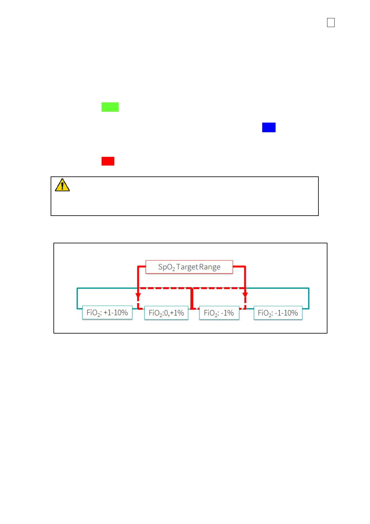
Figure 12-11: Diagram of the PRICO Algorithm
The PRICO algorithm works as outlined in the diagram above. After every 30 seconds, an FiO
2
adjustment is made based on the current SpO
2
and its position in one of the four regions.
• Outside the SpO
2
target range: the FiO
2
step size (1 to 10%) is determined by current SpO
2
,
trend of SpO
2
data and an extrapolation of SpO
2
data.
• Inside the SpO
2
target range: FiO
2
step of +1%, if FiO
2
is in lower half. If FiO
2
is in upper half
decrease FiO
2
by 1%.
• FiO
2
adjustments are made up to the pre-set FiO
2
limits (Min FiO
2
to Max FiO
2
).
 Loading...