2–2 Installation
Publication 1203–5.1 –– July, 1997
Switch SW3
Set switch SW3 first. The settings on this switch determine how the
SCANport device uses the data contained in the programmable
controller I/O image table. SW3 also establishes the minimum rack
size that this communications module requires.
The switches are labeled in the same orientation as they appear on
the board.
Table 2.A, SW3 Image Table Map, and Figure 2.2, SW3 Flowchart,
are included to help you set the DIP switches properly. It may also
be helpful to color in the final switch settings in Figure 2.1 as a
visual record of your SW3 settings. Chapter 3 contains several
examples of how to fill in the worksheet and set these DIP switches.
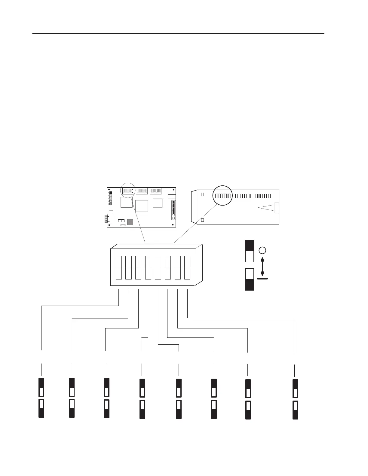
Figure 2.1
Configuration Switch SW3 Settings
J1
SW3
Block
Transfer
Off
Datalink A
Transfers
On
Logic
Command/Status
On
Off
Reference/
Feedback
On
Off
On
Off
Datalink B
Transfers
Datalink C
Transfers
On
Off
On
Off
On
Off
Datalink D
Transfers
81234567
OPEN
Truncate
➀➁
Last Datalink
➀
IMPORTANT: Only available on communications modules with version 1.02 or later firmware.
➁
All datalinks are two words, the truncate function will delete the last datalink word. (If “Datalink B” is the last used,
“Data in B2” and “Data Out B2” will be truncated.)
Open Style
Enclosed Style
Off
On
Not
Enabled
Enabled
Off (Open)
On
"

 Loading...