3–3Configuration and Interfacing
Publication 1203–5.1 –– July, 1997
DIP switch SW3 determines how the data contained in the
programmable controller I/O image table is used in the drive (Figure
3.2). The first three switches (1 through 3) select the basic control
features. Switches 4 through 7 support additional capability to
transfer selected parameter information between the drive and the
programmable controller. Products that have this capability have a
group of parameters for adapter I/O. These parameters are identified
as “Data In” and “Data Out” parameters. Each datalink switch on the
adapter consumes two words (unless truncated using SW3–8) in both
the input and output image table of the programmable controller.
The following are the rules for using datalink switches:
1. Normally, each datalink switch reserves two words in both the
input and output image tables of the programmable controller.
The starting module group/rack size switch (SW2, 1-2) on the
adapter must be set to support this.
2. The truncate last datalink switch truncates the last datalink to one
word in the input and output image table, instead of two. You can
use this to minimize the required rack size consumed by a
communications module.
3. Each set of datalink parameters in the drive can only be used by
one remote I/O communications module. If more than one
module is connected to a single SCANport link, the switch
settings must not conflict.
4. Parameter setting in the drive determine the data passed through
the datalink mechanism. Refer to the “Adapter I/O” group in the
drive manual for details.
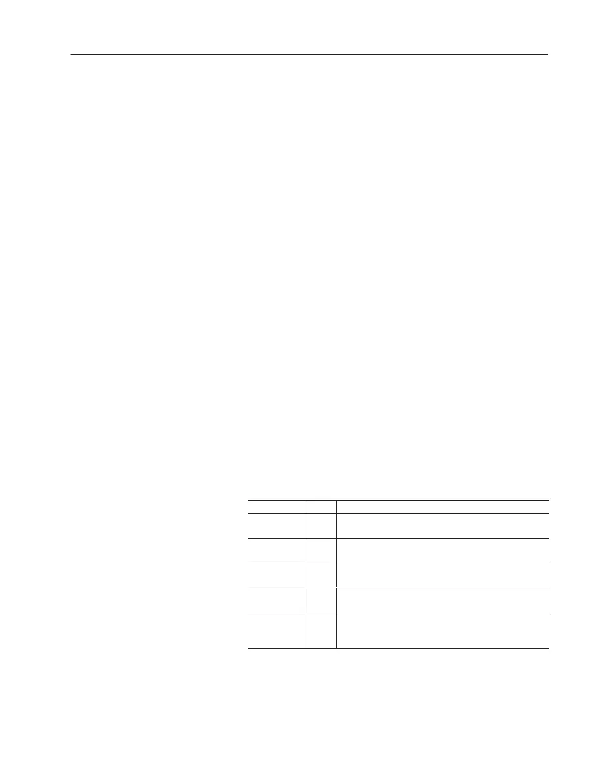
Table 3.A
Datalink Switch SW3 Settings
SW3 switch: State: Input and output parameter assignments in the drive:
DatalinkA
SW3–4
On
Off
Reserves Data In/Out A for this adapter
Data In/Out A not used by this adapter
Datalink B
SW3–5
On
Off
Reserves Data In/Out B for this adapter
Data In/Out B not used by this adapter
Datalink C
SW3–6
On
Off
Reserves Data In/Out C for this adapter
Data In/Out C not used by this adapter
Datalink D
SW3–7
On
Off
Reserves Data In/Out D for this adapter
Data In/Out D not used by this adapter
Truncate
Last Datalink
SW3–8
On
Off
Truncates the last datalink to one word
No truncation performed
Data Transfer Through the
Communications Module

 Loading...