2–9Installation
Publication 1203–5.1 –– July, 1997
The remote I/O communications module can be provided in three
mounting configurations:
• Open Style board factory installed in a drive (not available for all
drives)
• Open Style board as a separate kit
• Enclosed style for panel mount or DIN rail mount
This section provides mounting information for the Enclosed style
and the Open style kit.
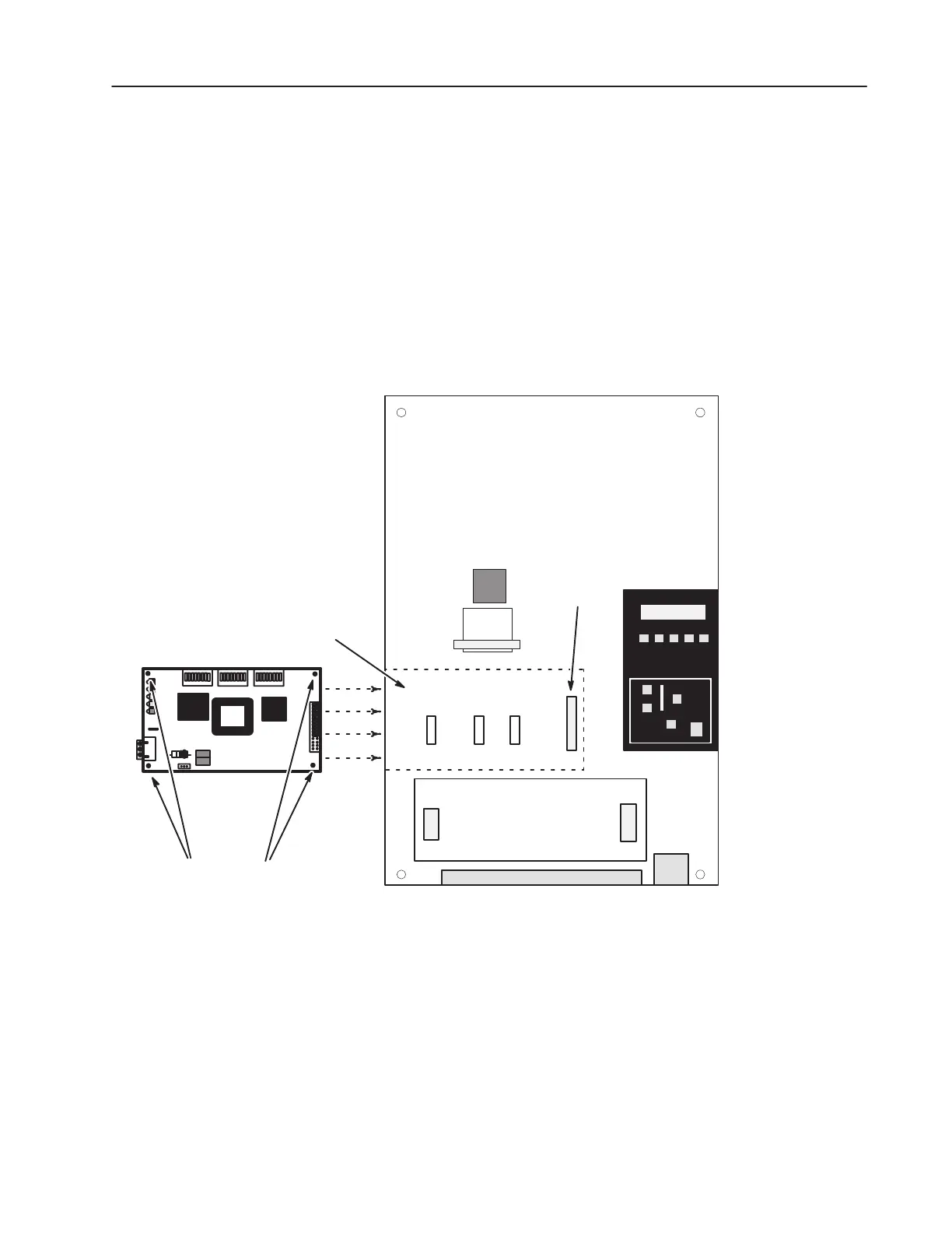
Figure 2.8
Open Style Communications Module Mounting Location (1336 Plus
7.5–500HP)
1336 PLUS Main Control Board
TB2
TB1
L OPTION
J7
J9
Human Interface
Module
J4
Open Communications Module
Mounts Here
Memory
Module
U44
J3
J1
U50 U54 U56
Mounting Screws & Standoffs Qty 4
SCANport 6
Install the board with the component side facing you.
Mounting the Remote I/O
Module
"

 Loading...