2–14 Installation
Publication 1203–5.1 –– July, 1997
You must terminate both ends of a remote I/O link to ensure proper
operation. This termination is required only at the ends of the
physical cable. Each remote I/O network should have exactly two
termination resistors installed. Use Table 2.D and Figure 2.12 and
Figure 2.13 to determine the proper termination for your particular
link. Termination resistor R3 is located on the board, and the J2
jumper selects this resistor.
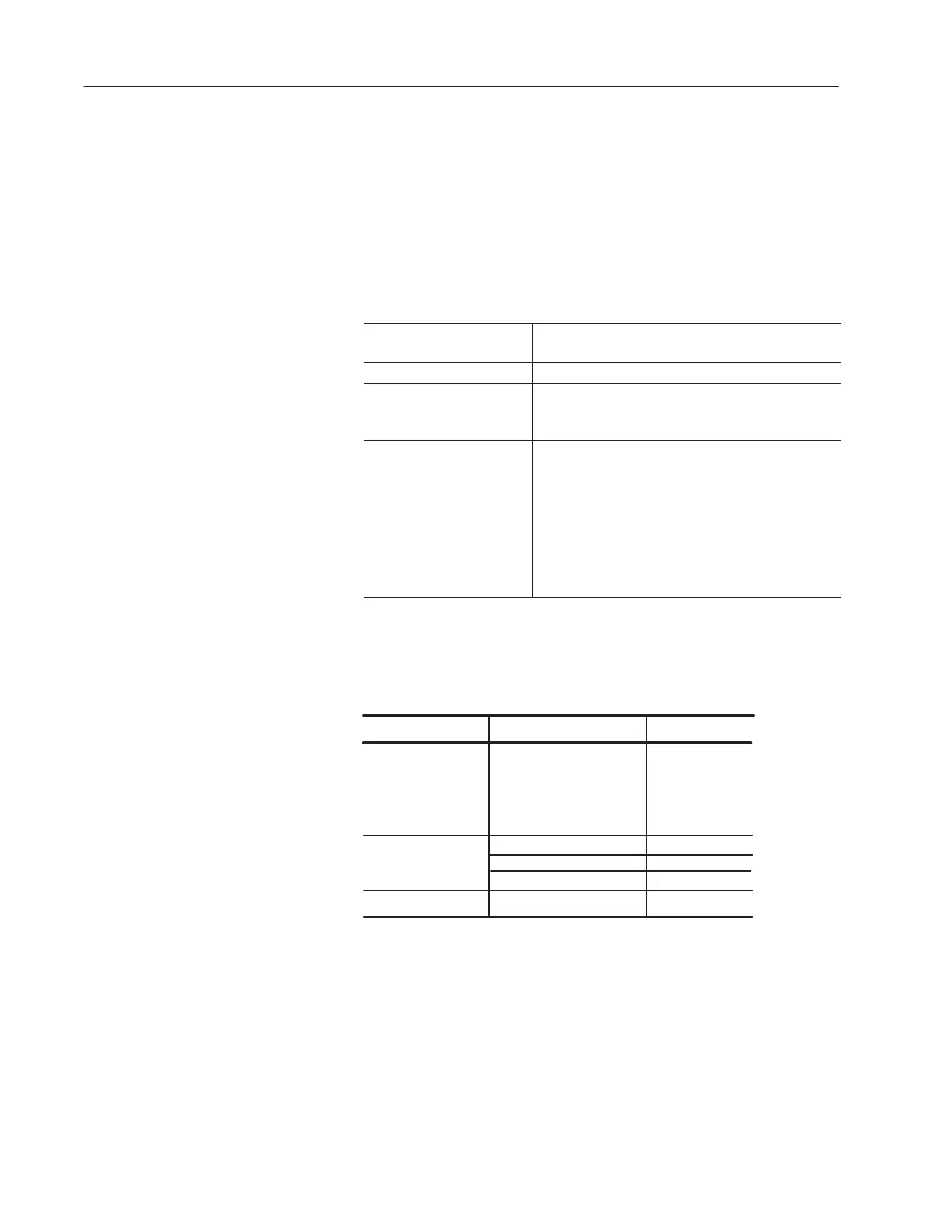
Table 2.D
Termination Resistor Requirements
If this device is an end
device of a remote I/O link:
Terminate the link by:
Programmable controller Refer to the manual for your model processor.
Open style, single point
remote I/O adapter
Set jumper J2 in position 1–2 for termination and 2–3 for
no termination as shown in Figure 2.12. The jumper
enables a 150 ohm resistor as the terminator resistor.
Enclosed style single point
remote I/O adapter
Connect a terminator resistor between the remote I/O
terminals labeled 1 and 2 as shown in Figure 2.13.
Use either a 150 Ohm or an 82 Ohm terminator.
•You must use an 82 Ohm resistor if the remote I/O link is
operating at 230.4 kbps (terminator must be connected at both
the scanner and the adapter).
•You should use an 82 Ohm resistor if the remote I/O link is
operating at 57.6 kbps or 115.2 kbps unless one of the devices
on the link is listed in Table 2.E. If you are using a device
listed in Table 2.E, then you must use a 150 Ohm terminator.
Important: The following products (Table 2.E) cannot be on a link
using 82-Ohm termination resistors.
Table 2.E
Unsupported Remote I/O Link Devices
Device Type Series
Scanners
Adapters
Miscellaneous
1771-SN
1772-SD, -SD2
1775-SR
1775-S4A, -S4B
6008-SQH1, -SQH2
All
Catalog Number
1771-AS
1772-ASB
1771-DCM
1771-AF
All
A
All
All
Connecting the
Termination Resistor

 Loading...