2–5Installation
Publication 1203–5.1 –– July, 1997
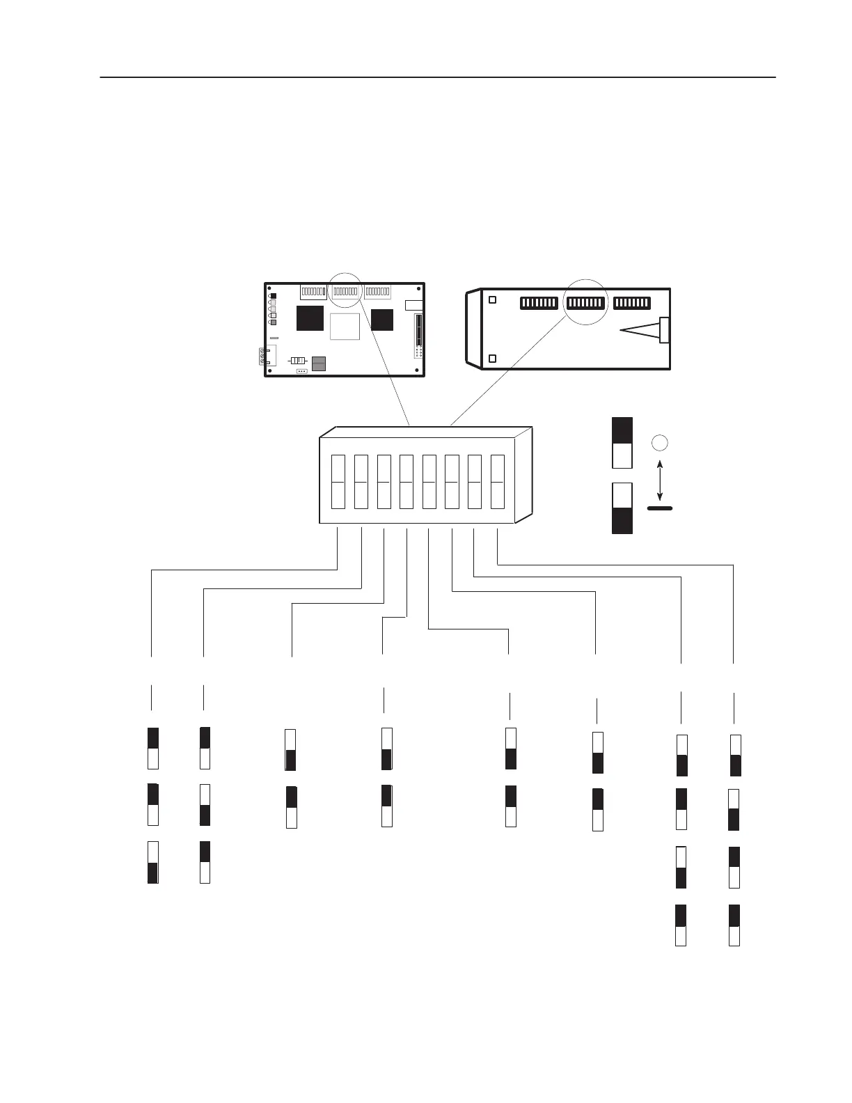
Switch SW2
Switch SW2 determines Rack Size, Last State, Rack Fault, and Bit
Rate Selections as shown in Figure 2.3.
The switches are labeled in the same orientation as they appear on
the board.
Figure 2.3
Configuration Switch SW2 Settings
On
J1
SW2
Starting Module Group➁
On
Last
Rack
Setting
➃
Hold
Last
State
➄
➅
Zero
Image
on PLC
Fault
Run at
Last State
Communications
Loss
➅
No
Fault
Fault on
Comm
Loss
On
RIO Baud Rate
57.6
kbps
115.2
kbps
230.4
kbps
Last
Rack
Not–
Last
Rack
Off
On
Off
Off Off
On
Off
On
Off
On
Off
Off
Off
On
Off
On
0
4
6
➀
If this switch is set to No Fault,
the setting of the Hold Last State
switch determines the data sent
to the SCANport device when the
PLC is in Reset/Program/Test.
81234567
OPEN
Off
Enclosed Style
Open Style
2
OFF (OPEN)
ON
No
Fault
➀
Fault
Drive
On
Off
➁
The setting of this switch is determined
by the amount of discrete I/O that will be
passed between the PLC and the drive.
Refer to Table 2.A for more information.
Reset/
Program/
Test
➂
➄
➂
This switch is active on
Firmware Version 2.xx
modules only. It is not used by
modules containing Firmware
Version 1.xx.
➃
Set this switch on the last
module used for a given rack
address. It does not
electrically terminate the RIO
link.
➄
Refer to Figure 2.4.
➅
Refer to Figure 2.5
and Figure 2.6.
"

 Loading...