256 Rockwell Automation Publication 750-IN001P-EN-P - April 2017
Chapter 5 I/O Wiring
Table 74 - TB2 Terminal Designations (One Relay and Two Transistor Outputs: 1R2T)
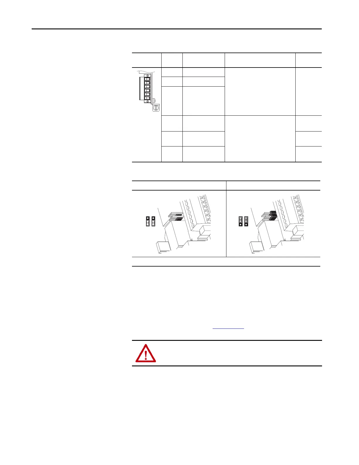
Table 75 - 24V DC Power Supply Source for Digital Inputs Jumpers
11-Series I/O with ATEX Option Module
The 11-Series I/O option module can be used with the ATEX option module,
catalog number 20-750-ATEX. For detailed information on installation of 11-
Series I/O with the ATEX option module, see the PowerFlex 750-Series
ATEX User Manual, publication 750-UM003
.
Relay Out Terminal Name Description Related
Parameter
R0NO Relay 0 N.O. Relay normally open contact output:
240V AC, 24V DC, 3.5 A max
General-purpose (inductive)/resistive
Relay normally closed contact output:
240V AC, 24V DC, 5 A max
Only resistive
10, 100, 101,
105, 106
On port X
R0C Relay 0 common
R0NC Relay 0 N.C.
T0 Transistor output 0 Transistor output
Rating: 24V DC = 1 A max including
U.L. applications
Resistive
20
On port X
TC Transistor output
common
T1 Transistor output 1 30
On port X
Internal External
IMPORTANT: 24V DC supply is only used with modules 20-750-1132C-2R and 20-750-1133C-1R2T.
ATTENTION: You cannot use the ATEX card with the 11-series I/O card in port
7 when used in an Integrated Motion on EtherNet/IP application.
P3 P8
3
1
3
1
 Loading...

