EasyManua.ls Logo

Allen-Bradley 5069-IB8S User Manual

Allen-Bradley 5069-IB8S
296 pages
To Next Page IconTo Next Page
To Previous Page IconTo Previous Page
Page #79 background imageLoading...
Page #79 background image
Rockwell Automation Publication 5069-UM004A-EN-P - April 2019 79
Features Common to Compact 5000 I/O Digital Modules Chapter 2
Synchronized Sampling lets you configure a test stand, for example, and take
many measurements simultaneously across many modules, if needed, while still
precisely coordinating the sampling. With these modules, the synchronized
sampling coordinates within approximately ± 10 μs.
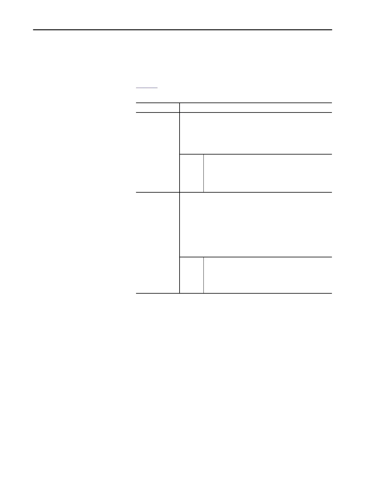
Table 12 describes how you can use time stamps.
Table 12 - Timestamp Options
Topic Description
Timestamping for a
sequence of events
You can use CIP Sync to establish a sequence of events occurring at a particular input
module point by timestamping the input data. To determine a sequence of events, you
must complete the following:
Set the format of the input module to Timestamped Input Data.
Enable COS for the input where a sequence occurs, and disable COS for all other points
on the module.
TIP
If you configure multiple inputs for COS, your module generates a unique
time stamp each time any of those inputs change state if the changes do
not occur within 500 μs of each other.
If multiple inputs that are configured for COS change state within 500 ìs of
each other, one time stamp is generated for all state changes. As a result, it
appears as if they changed simultaneously.
Timestamping with
scheduled outputs
You can use timestamping with the scheduled outputs feature, so that after input data
changes state and a time stamp occurs, an output point actuates at a specific time.
You can schedule outputs into the future. Outputs that are sent in one packet can differ by
approximately 2 seconds. Sending in multiple messages allows greater spacing between
schedules. When you use timestamping of inputs and scheduled outputs, you must
complete the following:
Choose a connection format for each input and output module that enables
timestamping.
Disable COS for all input points on the input module except the point being
timestamped.
TIP
For scheduled outputs to work most effectively, remember the following:
The schedule fires when it is configured to. You must make sure that
there is enough time for the schedule to plan ahead. If you are using an
MAOC instruction, you cannot control the schedule.
A system-level Grandmaster synchronizes the times of the I/O modules.

Table of Contents

Question and Answer IconNeed help?

Do you have a question about the Allen-Bradley 5069-IB8S and is the answer not in the manual?

Allen-Bradley 5069-IB8S Specifications

General IconGeneral
CategoryI/O Systems
ManufacturerAllen-Bradley
Product TypeDigital Input Module
Input Channels8
Input Voltage Category24V DC
Voltage Rating24V DC
Enclosure Type RatingNone (open-style)
CommunicationEtherNet/IP
Connection TypeRemovable Terminal Block
Off-State Voltage≤ 5V DC
On-State Input Voltage15…30V DC
Off-State Input Voltage≤ 5V DC
Module LocationLocal
Isolation Voltage50V (continuous), Basic Insulation
Operating Temperature0-60°C
CertificationscULus, CE
Off-State Current1.5 mA max

Summary

Chapter 1 Digital Module Operation in a Control System

Controller and Software Compatibility

Details controller and Logix Designer application compatibility requirements.

Power the Modules

Details the MOD power and SA power requirements for system operation.

Configure the Modules

Guides on creating a Logix Designer project and transferring configuration data.

Chapter 2 Features Common to Compact 5000 I/O Digital Modules

Electronic Keying

Reduces risk of using wrong devices by comparing project definition to installed device.

Chapter 3 Input Module Features

Module Health Diagnostic

Explains the status indicator on the module front for indicating module health.

Chapter 4 Output Module Features

Fault and Status Reporting

Details how output modules report fault and status data.

Chapter 5 Safety Module Features

Safety Application Suitability Levels

Details suitability levels for safety applications based on standards like IEC 61508.

Chapter 6 Configure a Standard Module

Chapter 7 Configure and Replace Safety Modules

Edit the Module Configuration Common Categories

Explains configuring common parameters for safety modules.

Replace a Safety Module

Provides procedures for replacing safety modules on a CIP Safety network.

Appendix A Troubleshoot Your Module

Use the Logix Designer Application for Troubleshooting

Details how to use Logix Designer to identify and resolve fault conditions.

Appendix D Safety Data for Safety Modules

Compact 5000 I/O Safety Input Module Safety Data

Lists calculated safety data (PFD, PFH) for safety input modules.

Compact 5000 I/O Safety Output Module Safety Data

Lists calculated safety data (PFD, PFH) for safety output modules.

Related product manuals