1785-UM022B-EN-P - February 2002
Planning to Use Your ControlNet PLC-5 Processor 2-25
First Rule of
Module Optimization
When placing discrete modules, put the type (input or output) you
have the least of to the left in the chassis.
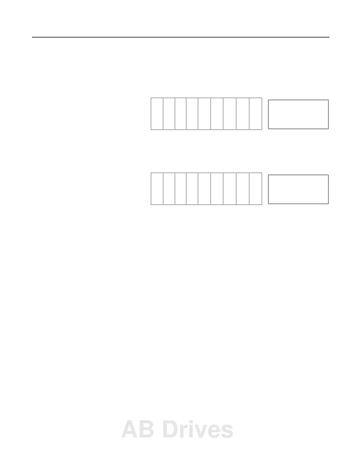
Example 3
Some chassis may contain analog modules, communication cards, or
power supplies. Examine the following chassis:
This chassis contains an analog module and a power supply. Assume
all analog modules on a ControlNet network are mapped to an integer
table in the PLC-5 processor. Power supplies do not require any I/O
image table. Therefore, the optimal configuration of this chassis is:
Since analog modules and power supplies do not need any I/O image
space you should place them to the right so that you don’t have to
waste any inputs or outputs passing over these modules. This leads to
the second important module placement rule of optimization.
Input file Input size Output file Output size
I:010 6 O:010 2
ACN A
I
O
IO
PS I = Discrete Input Module
O = Discrete Output Module
ACN = ControlNet adapter
A = Analog Module
PS = Power Supply
II
ACN O O I I I I
I = Discrete Input Module
O = Discrete Output Module
ACN = ControlNet adapter
A = Analog Module
PS = Power Supply
APS
AB Drives