1785-UM022B-EN-P - February 2002
2-26 Planning to Use Your ControlNet PLC-5 Processor
Second Rule of
Module Optimization
Place modules that do not require I/O image table space to the right
in the chassis.
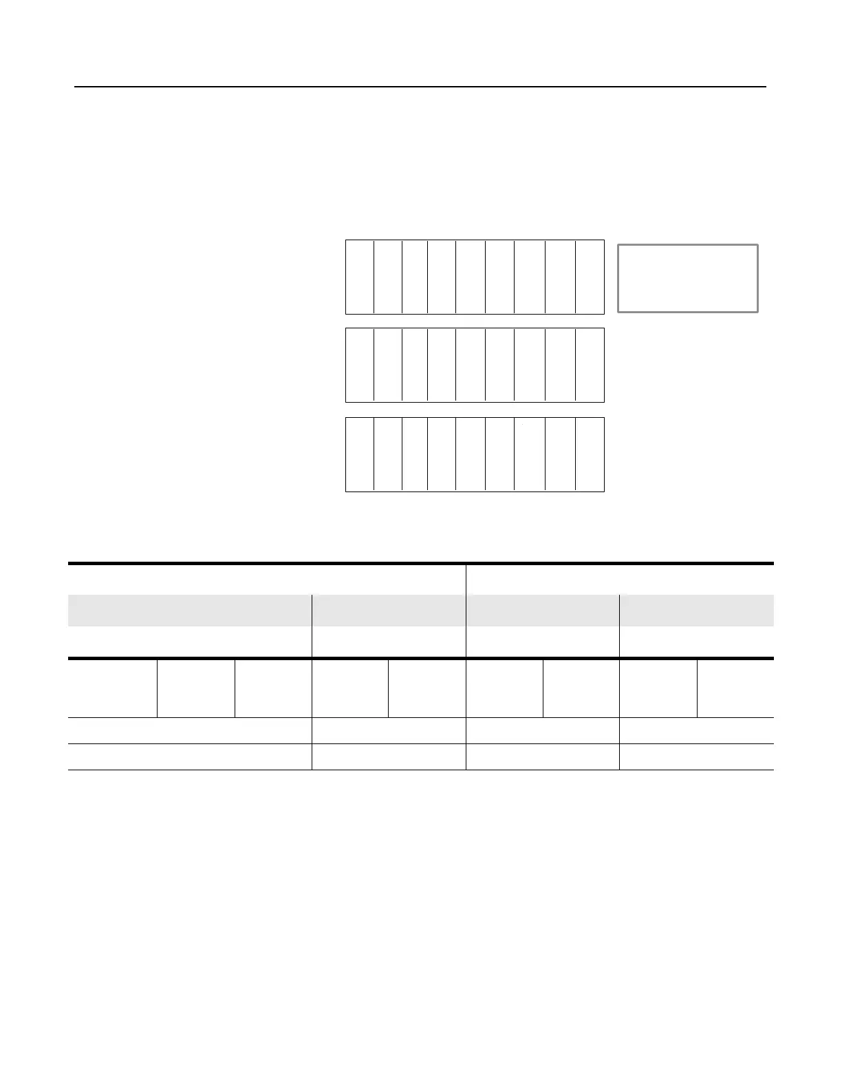
Example 4
To understand how optimization with a ControlNet network preserves
I/O image space, look at the following example system:
The following chart shows how a Remote I/O system compares to
one optimized with a ControlNet network.
If you install the system on a PLC-5/20C processor, the Remote I/O
network option would be out of I/O image space, while the
ControlNet network option would have used only one-third of the
available I/O image space. You must take into account future
expansion when optimizing the I/O.
I = Discrete Input Module
O = Discrete Output Module
ACN = ControlNet adapter
A = Analog Module
PS = Power Supply
Chassis 1
Chassis 2
Chassis 3
ACN A A A A A
a
APS
A
A
ACN I O O O O O O PS
ACN O I I I I I I PS
Remote I/O ControlNet Network
Input Output Input Output
Chassis Address Size Address Size Address Size Address Size
1
2
3
I:010
I:020
I:030
8
8
8
O:010
O:010
O:030
8
8
8
I:010
I:011
n/a
1
7
0
O:010
O:017
n/a
7
1
0
Total Used 24 (3 racks) 24 (3 racks) 8 (1 rack) 8
Remaining 0 0 16 (2 racks) 16

 Loading...


