24 Rockwell Automation Publication 2080-UM003A-EN-E - March 2013
Chapter 3 Wiring Connections
Allen-Bradley 1492 wiring systems are available for connecting the I/O module
to external I/O. These wiring systems include a pre-wired cable available in four
lengths: 0.5m (1.6 feet), 1.0m (3.3 feet), 2.5m (8.2 feet), 5.0m (16.4 feet). An
Interface Module for connecting external devices is also available. Cables are
equipped with keyed connectors at both ends for proper connections. Interface
modules are DIN rail mountable and are available with or without field side
status indicating LEDs. Stick-on labels are provided with the Interface modules to
identify I/O wiring termination points.
Summary
This chapter covered the input and output wiring connections for the different
analog and discrete Micro800 expansion I/O modules.
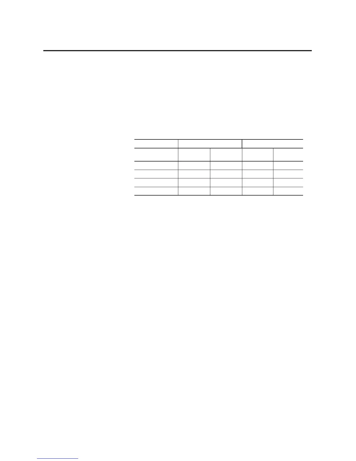
1492 Cables
Catalog No. Voltage Drop @ 30 °C Voltage Drop @ 60 °C
Series C Cables V DC and DC
Com Wires
(1)
(1) Voltage drop @ maximum rated current of 2 amps per conductor.
Output Channel
Wires
(2)
(2) Voltage drop at maximum rated current of 0.5 amps per output channel.
V DC and DC
Com Wires
Output
Channel Wires
1492-CABLE005H 127 mv 34 mv 144 mv 38 mv
1492-CABLE010H 173 mv 45 mv 196 mv 51 mv
1492-CABLE025H 334 mv 83 mv 388 mv 95 mv
1492-CABLE050H 574 mv 147 mv 686 mv 169 mv

 Loading...


