50 Rockwell Automation Publication 2080-UM003A-EN-E - March 2013
Appendix A Specifications
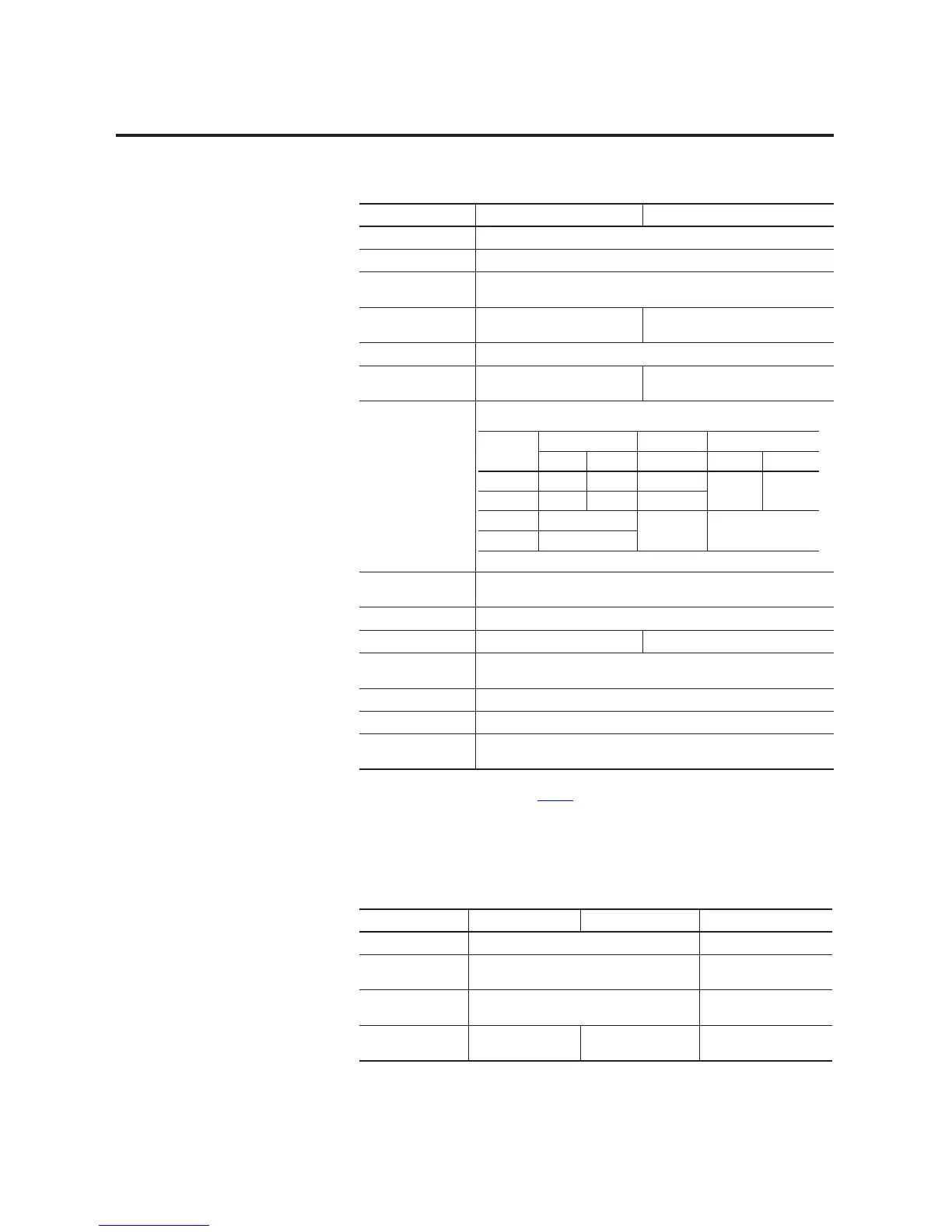
Analog Expansion I/O
Wiring category
(1)
2 – on signal ports
Wire type Copper
Terminal screw
torque. max
0.5…0.6 Nm
(4.4…5.3 lb-in.)
(2)
Bus current draw, max 5V DC, 120 mA
24V DC, 50 mA
5V DC, 160 mA
24V DC, 100 mA
Load current, max 2 A
Power dissipation,
total
2.72 W 5.14 W
Relay contact,
(0.35 power factor)
Minimum load, per
point
10 mA per point
Off-state leakage, max 1.5 mA
Status indicators 8 yellow indicators 16 yellow indicators
Isolation voltage 240V (continuous), Reinforced Insulation Type, channel to system
Type tested @ 3250V DC for 60 s
Pilot duty rating C300, R150
Enclosure type rating Meets IP20
North American temp
code
T4
(1) Use this Conductor Category information for planning conductor routing. Refer to Industrial Automation Wiring
and Grounding Guidelines, publication 1770-4.1
.
(2) RTB hold down screws should be tightened by hand. They should not be tightened using a power tool.
2085-OW8 and 2085-OW16 Relay Output Module
Attribute 2085-OW8 2085-OW16
Max
Volts
Amperes Amperes Volt Amperes
Make Break Continuous Make Break
120V AC 15 A 1.5 A 2.0 A 1800V A 180V A
240V AC 7.5 A 0.75 A
24V DC 1.0 A 1.0 A 28V A
125V DC 0.22 A
2085-IF4, 2085-IF8, 2085-OF4 Analog Input and Output Modules
Attribute 2085-IF4 2085-OF4 2085-IF8
Number of I/O 4 8
Dimensions, HxWxD 28 x 90 x 87 mm
(1.1 x 3.54 x 3.42 in.)
44.5 x 90 x 87 mm
(1.75 x 3.54 x 3.42 in.)
Shipping weight,
approx.
140 g (4.93 oz) 220 g (7.76 oz)
Bus current draw,
max
5V DC, 100 mA
24V DC, 50 mA
5V DC, 160 mA
24V DC, 120 mA
5V DC, 110 mA
24V DC, 50 mA

 Loading...


