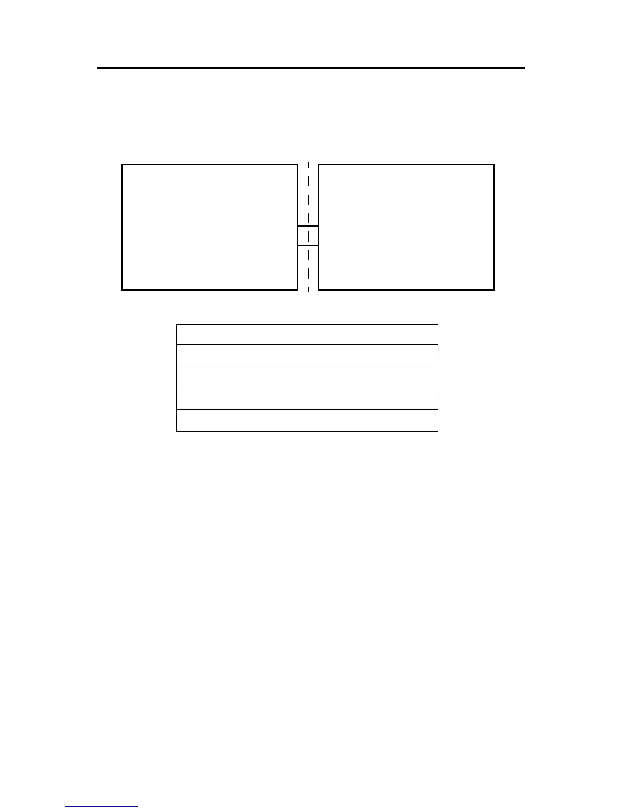
Hazardous Location
Class 1 Division 2,
Groups A, B, C, and D
Non-Hazardous Location
Micro800 Controller
USB Port
J3
V
max
= 5V DC
I
max
= 500 μA
L
i
= 1 μH
C
i
= 120 pF
Any associated apparatus with Universal
Serial Bus (USB) connection
USB Port
V
oc
, I
sc
, L
a
and C
a
to be determined per
Capacitance and Inductance Values table
Capacitance and Inductance Values
Nonincendive Equipment Associated Apparatus
V
max
(or U
i
) ≥ V
oc
or V
t
(or U
o
)
I
max
(or L
i
) ≥ I
sc
or I
t
(or I
o
)
C
i
+ C
cable
≤ C
a
(or C
o
)
L
i
+ L
cable
≤ L
a
(or L
o
)
Capacitance and Inductance of the field wiring from the nonincendive equipment to the associated
apparatus shall be calculated and must be included in the system calculations as shown in the table above.
Where the cable capacitance and inductance per foot are not known, the following values shall be used:
C
cable
= 60 pF/ft, L
cable
= 0.2 μH/ft.
Wiring method must be in accordance with ANSI/NFPA70.

 Loading...


