Micro850 24-Point Programmable Controllers 9
Publication 2080-IN007A-EN-P - September 2012
Mount the Module
Most applications require installation in an industrial enclosure to reduce the effects of
electrical interference and environmental exposure. Locate your controller as far as possible
from power lines, load lines, and other sources of electrical noise such as hard-contact
switches, relays, and AC motor drives. For more information on proper grounding guidelines,
see the Industrial Automation Wiring and Grounding Guidelines, publication 1770-4.1
.
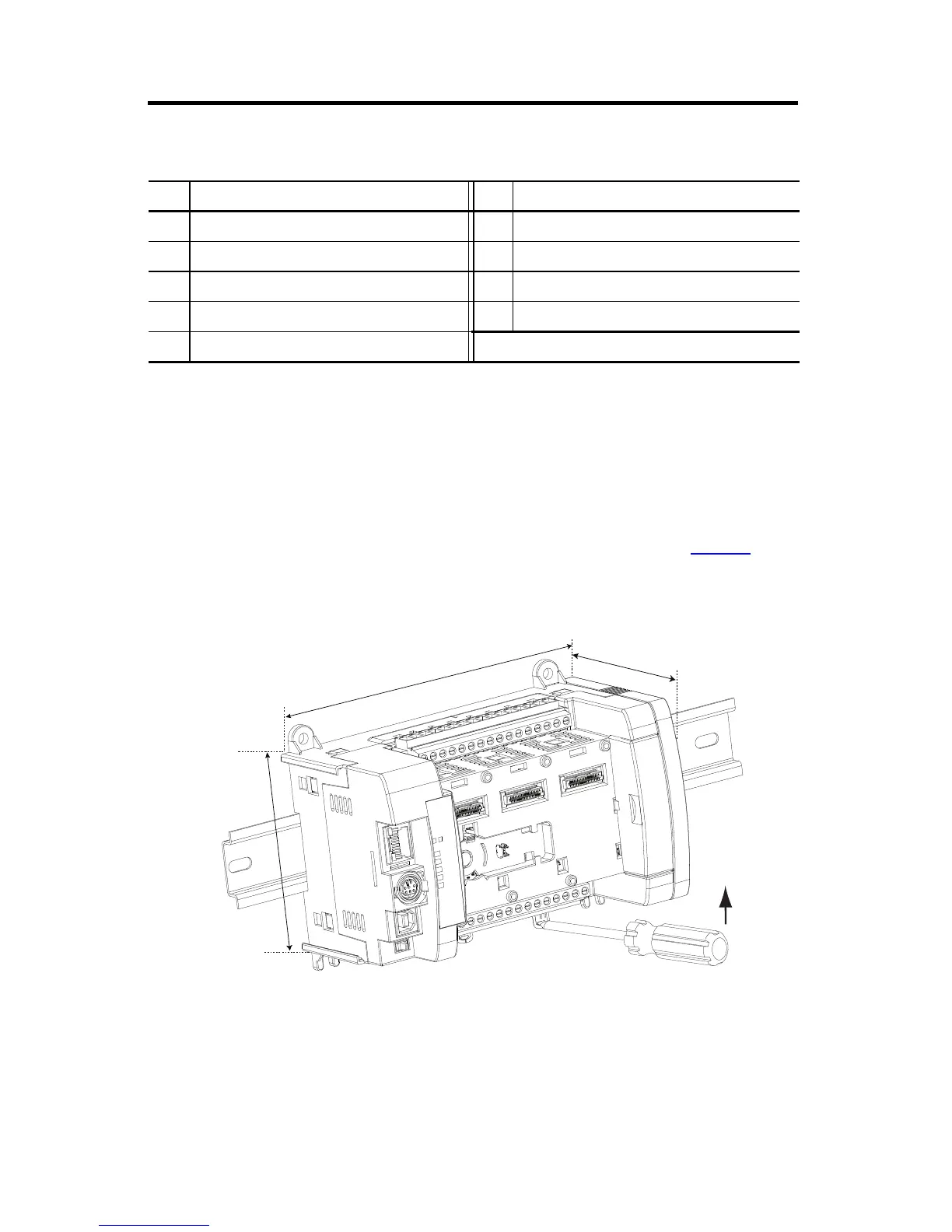
Mounting Dimensions and DIN Rail Mounting
Module Spacing
Maintain spacing from objects such as enclosure walls, wireways and adjacent equipment.
Allow 50.8 mm (2.0 in.) of space on all sides for adequate ventilation. If optional
accessories/modules are attached such as the power supply 2080-PS120-240VAC or
Status Indicator Description
Description Description
16 Input status 21 Fault status
17 Module Status 22 Force status
18 Network Status 23 Serial communications status
19 Power status 24 Output status
20 Run status
45912
Mounting dimensions do not include mounting feet or DIN rail latches.
158 mm (6.22 in.)
80 mm (3.15 in.)
90 mm (3.54 in.)

 Loading...


