Publication 1762-UM001D-EN-P - March 2004
Installing Your Controller 2-13
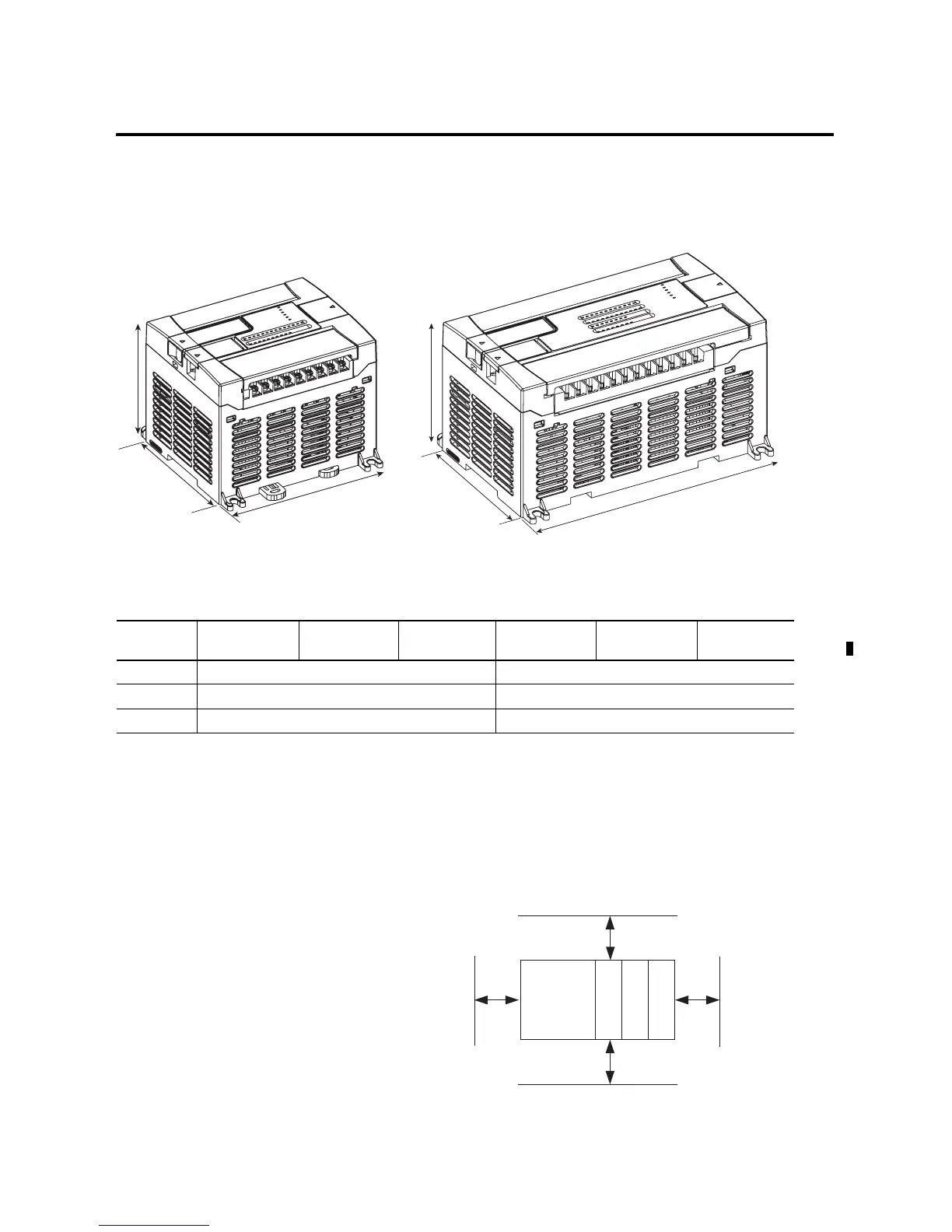
Controller Mounting
Dimensions
Controller and
Expansion I/O Spacing
The controller mounts horizontally, with the expansion I/O extending
to the right of the controller. Allow 50 mm (2 in.) of space on all sides
of the controller system for adequate ventilation. Maintain spacing
from enclosure walls, wireways, adjacent equipment, etc., as shown
below.
Table 2.1 Controller Dimensions
Dimension 1762-L24AWA
1762-L24AWAR
1762-L24BWA
1762-L24BWAR
1762-L24BXB
1762-L24BXBR
1762-L40AWA
1762-L40AWAR
1762-L40BWA
1762-L40BWAR
1762-L40BXB
1762-L40BXBR
A 90 mm (3.5 in.) 90 mm (3.5 in.)
B 110 mm (4.33 in.) 160 mm (6.30 in.)
C 87 mm (3.43 in.) 87 mm (3.43 in.)
C
B
A
C
B
A
1762-L24AWA, 1762-L24BWA, 1762-L24BXB
1762-L24AWAR, 1762-L24BWAR, 1762-L24BXBR
1762-L40AWA, 1762-L40BWA, 1762-L40BXB
1762-L40AWAR, 1762-L40BWAR, 1762-L40BXBR
MicroLogix
1200
1762 I/O
1762 I/O
1762 I/O
Side Side
Top
Bottom

 Loading...


