Publication 1762-UM001D-EN-P - March 2004
4-14 Communication Connections
For additional information on connecting the AIC+, refer to the
Advanced Interface Converter (AIC+) User Manual, publication
1761-6.4.
Cable Selection Guide
Item Description
1 Port 1 - DB-9 RS-232, DTE
2 Port 2 - mini-DIN 8 RS-232 DTE
3 Port 3 - RS-485 Phoenix plug
4 DC Power Source selector switch
(cable = port 2 power source,
external = external power source connected to item 5)
5 Terminals for external 24V dc power supply and chassis ground
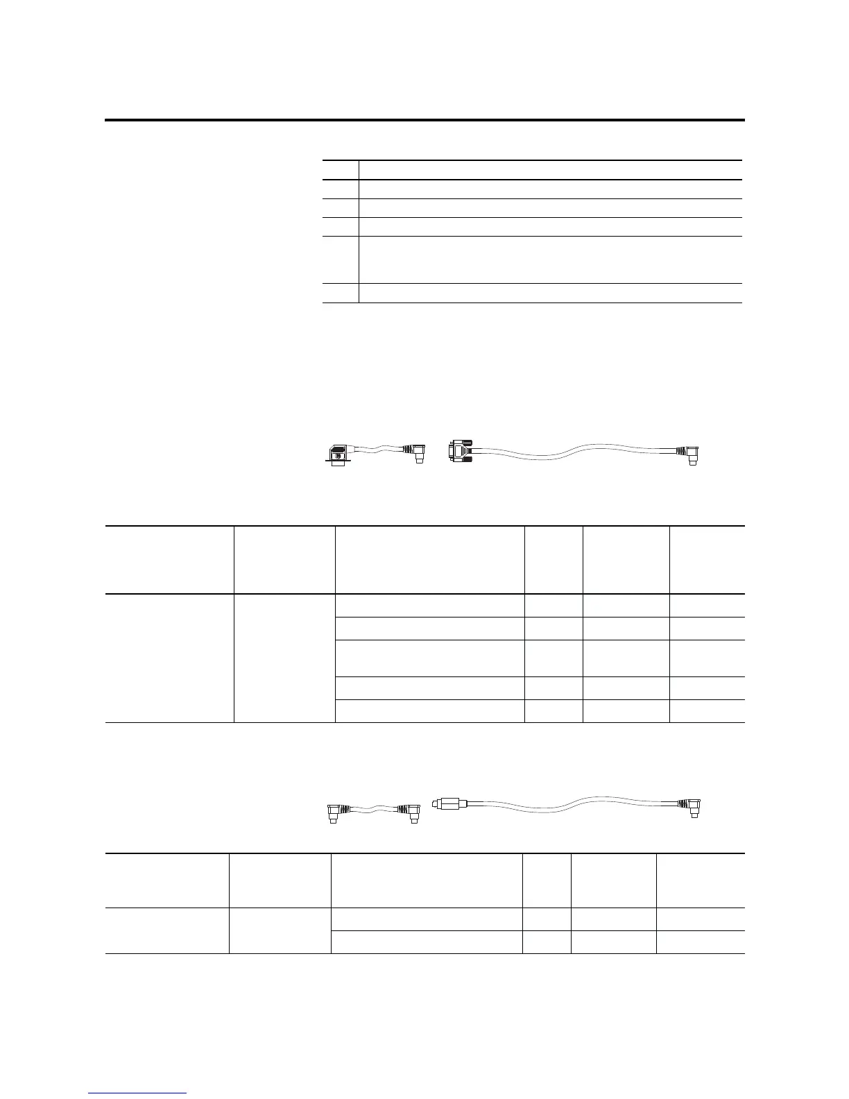
1761-CBL-PM02
(2)
1761-CBL-AP00
(2)
Cable Length Connections from to AIC+ External
Power Supply
Required
(1)
Power
Selection
Switch
Setting
(1)
1761-CBL-AP00
(2)
1761-CBL-PM02
(2)
45 cm (17.7 in)
2m (6.5 ft)
SLC 5/03 or SLC 5/04 processors, ch 0 port 2 yes external
MicroLogix 1000, 1200, or 1500 port 1 yes external
PanelView 550 through NULL modem
adapter
port 2 yes external
DTAM Plus / DTAM Micro port 2 yes external
PC COM port port 2 yes external
(1)
External power supply required unless the AIC+ is powered by the device connected to port 2, then the selection switch should be set to cable.
(2)
Series C or higher cables are required.
1761-CBL-HM02
(2)
1761-CBL-AM00
(2)
Cable Length Connections from to AIC+ External
Power Supply
Required
(1)
Power
Selection
Switch Setting
1761-CBL-AM00
(2)
1761-CBL-HM02
(2)
45 cm (17.7 in)
2m (6.5 ft)
MicroLogix 1000, 1200, or 1500 port 2 no cable
to port 2 on another AIC+ port 2 yes external
(1)
External power supply required unless the AIC+ is powered by the device connected to port 2, then the selection switch should be set to cable.

 Loading...


