Publication 1762-UM001D-EN-P - March 2004
6-2 Using Real-Time Clock and Memory Modules
Writing Data to the Real-Time Clock
When valid data is sent to the real-time clock from the programming
device or another controller, the new values take effect immediately.
The real-time clock does not recognize or accept invalid date or time
data.
Use the Disable Clock button in your RSLogix programming software
to disable the real-time clock before storing a module. This decreases
the drain on the RTC battery during storage.
RTC Battery Operation
The real-time clock has an internal battery that is not replaceable. The
RTC Function File features a battery low indicator bit (RTC:0/BL),
which shows the status of the RTC battery. When the battery is low,
the indicator bit is set (1). This means that the battery may fail within
14 days and the real-time clock module needs to be replaced. When
the battery low indicator bit is clear (0), the battery level is acceptable
or a real-time clock is not attached.
If the RTC battery is low and the controller is powered, the RTC
operates normally. If the controller power is removed and the RTC
battery is low, RTC data is lost.
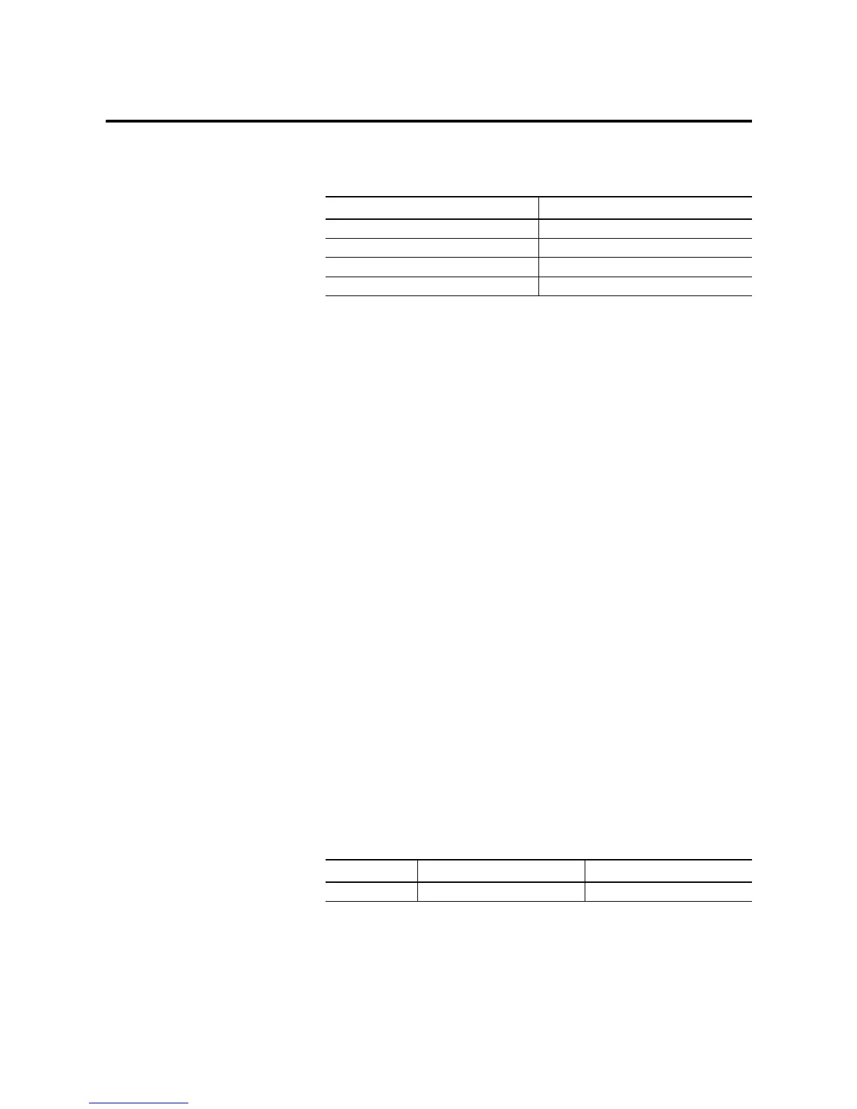
Table 6.1 RTC Accuracy
Ambient Temperature
Accuracy
(1)
(1)
These numbers are maximum worst case values over a 31-day month.
0°C (+32°F) +34 to -70 seconds/month
+25°C (+77°F) +36 to -68 seconds/month
+40°C (+104°F) +29 to -75 seconds/month
+55°C (+131°F) -133 to -237 seconds/month
Life Span Operating Temperature
Storage Temperature
(1)
(1)
Stored for six months.
5 years +0°C to +40°C (+32°F to +104°F) -40°C to +60°C (-40°F to +140°F)

 Loading...


