Publication 1762-UM001D-EN-P - March 2004
4-16 Communication Connections
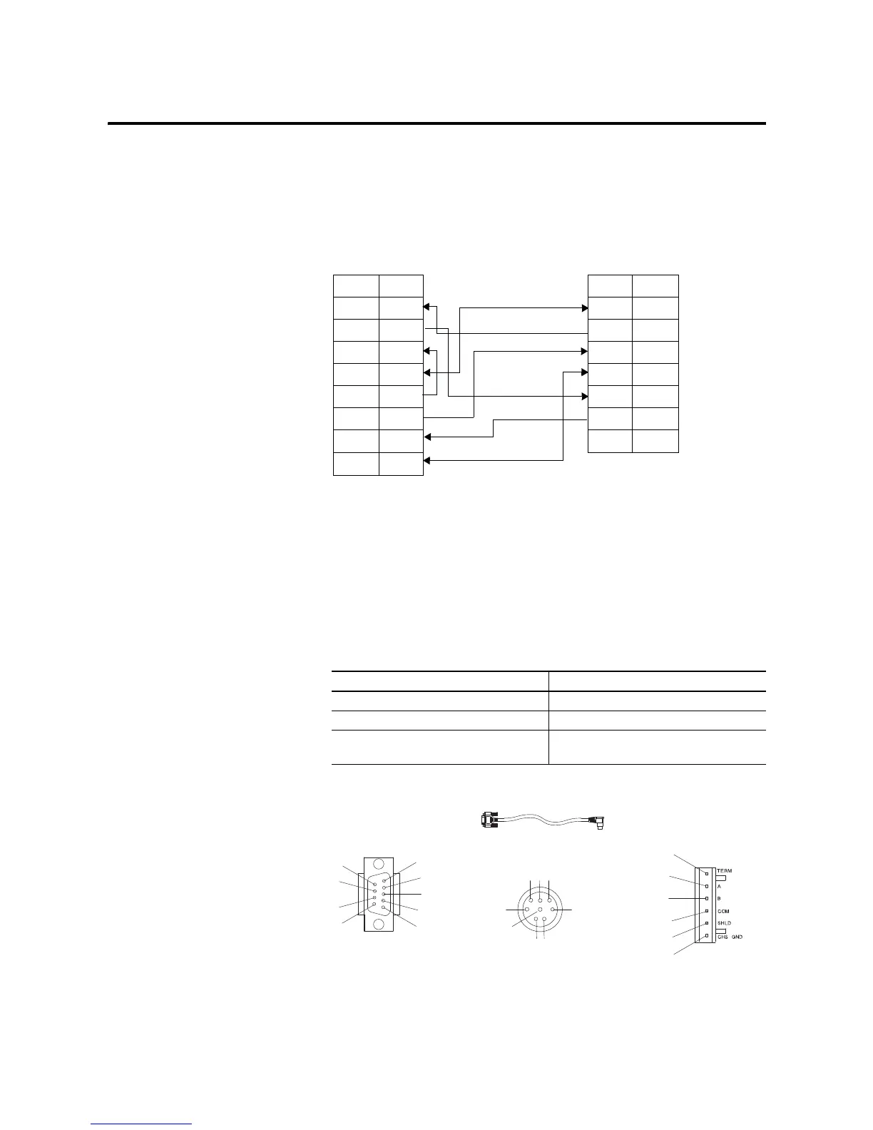
1761-CBL-PM02 Series C (or equivalent) Cable Wiring Diagram
Recommended User-Supplied Components
These components can be purchased from your local electronics
supplier.
Table 4.6 User Supplied Components
Component Recommended Model
external power supply and chassis ground power supply rated for 20.4 to 28.8V dc
NULL modem adapter standard AT
straight 9-25 pin RS-232 cable see table below for port information if
making own cables
Programming
Device
Controller
9-Pin D-Shell 8-Pin Mini Din
9RI 24V1
8CTS GND2
7RTS RTS3
6 DSR RXD 4
5GND DCD5
4DTR CTS6
3TXD TXD7
2RXD GND8
1DCD
1761-CBL-AP00 or 1761-CBL-PM02
DB-9 RS-232
RS-485 connector
cable straight D connector
Port 1
Port 2
Port 3
6
7
8
9
1
2
3
4
5
4
1
2
5
876
3
6
5
4
3
2
1

 Loading...


