Publication 1762-UM001D-EN-P - March 2004
Wiring Your Controller 3-11
wired on the group. Refer to pages 3-12 through 3-16 for sinking and
sourcing wiring diagrams.
1762-L24AWA, 1762-L24BWA, 1762-L24BXB, 1762-L24AWAR,
1762-L24BWAR and 1762-L24BXBR Wiring Diagrams
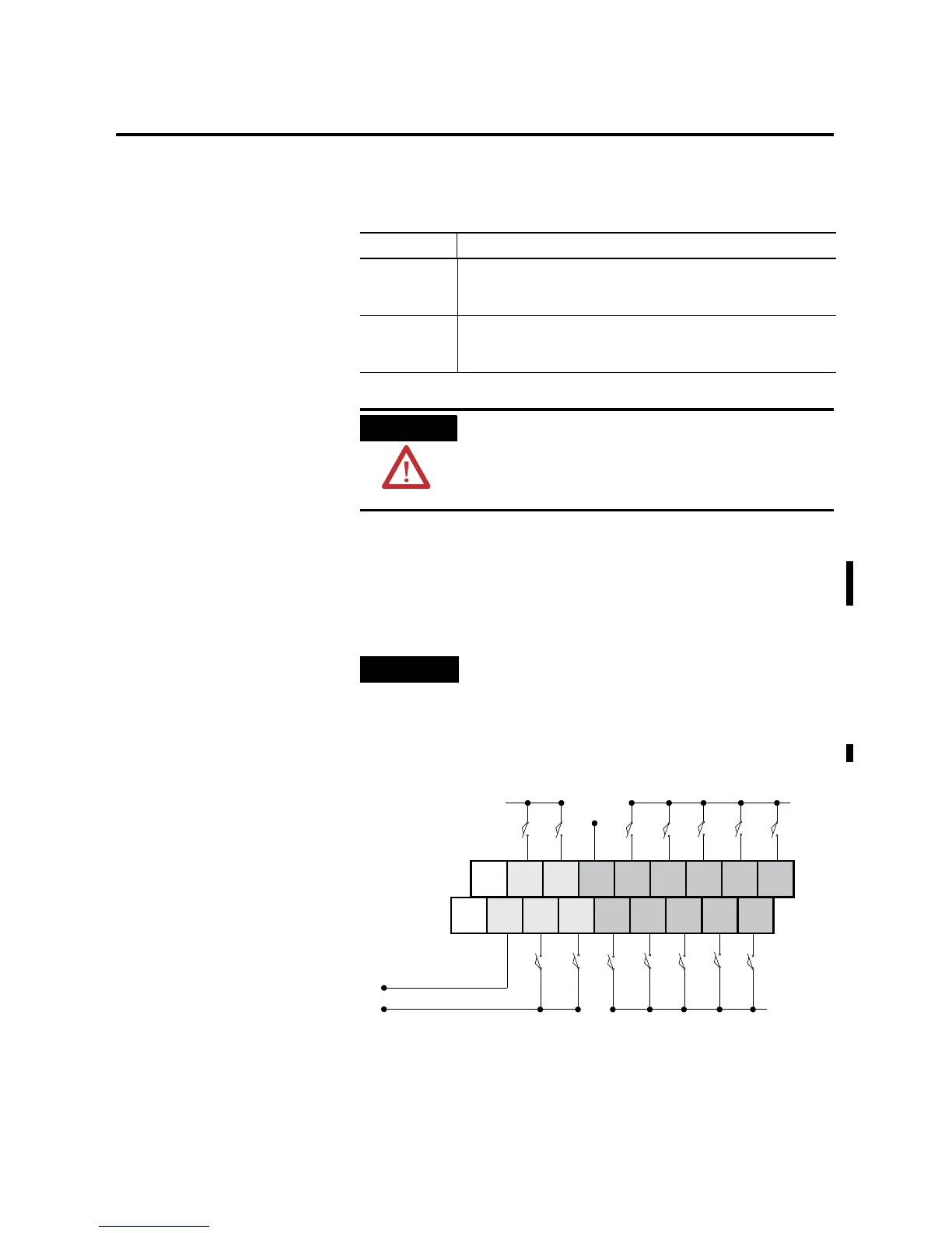
Figure 3.7 1762-L24AWA and 1762-L24AWAR Input Wiring Diagram
(1)
(1) “NC” terminals are not intended for use as connection points.
Type Definition
Sinking Input The input energizes when high-level voltage is applied to the input
terminal (active high). Connect the power supply VDC (-) to the input
group’s COM terminal.
Sourcing Input The input energizes when low-level voltage is applied to the input
terminal (active low). Connect the power supply VDC (+) to the input
group’s COM terminal.
ATTENTION
The 24V dc sensor power source must not be used to
power output circuits. It should only be used to
power input devices (e.g. sensors, switches). See
Master Control Relay on page 2-8 for information on
MCR wiring in output circuits.
TIP
In the following diagrams, lower case alphabetic
subscripts are appended to common-terminal
connections to indicate that different power sources
may be used for different isolated groups, if desired.
L1a
L1bL1a
L1b
L2a
L2b
IN 0 IN 2 IN 5 IN 7 IN 9
COM
1
IN 11 IN 13
NC
COM
0
IN 1 IN 3 IN 4 IN 6 IN 8 IN 10 IN 12
NC

 Loading...


