English-6 PowerFlex 70 Adjustable Frequency AC Drive Quick Start
Step 3 Wire the Drive – Wire Recommendations
Type Wire Type(s) Description
Min. Insulation
Rating
Power
(1)
Standard 600V, 90°C (194°F)
XHHW2/RHW-2
Anixter
B209500-B209507, Belden
29501-29507, or
equivalent
• Four tinned copper
conductors with XLPE
insulation.
• Copper braid/aluminum foil
combination shield and
tinned copper drain wire.
• PVC jacket.
Signal
(1) (2) (3)
Standard
Analog I/O
Belden 8760/9460(or
equiv.)
0.750 mm
2
(18AWG), twisted
pair, 100% shield with drain.
300V,
75-90 degrees
C (167-194
degrees F)
Belden 8770(or equiv.) 0.750 mm
2
(18AWG), 3
cond., shielded for remote pot
only.
Digital I/O
(1) (2) (3)
Shielded Multi-conductor shielded
cable such as Belden
8770(or equiv.)
0.750 mm
2
(18AWG), 3
conductor, shielded.
300V,
60 degrees C
(140 degrees F)
(1)
Control and signal wires should be separated from power wires by at least 0.3 meters (1 foot).
(2)
If the wires are short and contained within a cabinet which has no sensitive circuits, the use of
shielded wire may not be necessary, but is always recommended.
(3)
I/O terminals labeled “(–)” or “Common” are not referenced to earth ground and are designed to
greatly reduce common mode interference. Grounding these terminals can cause signal noise.
Terminal Block Specifications
Name Frame Description
Wire Size Range
(1)
Torque
Maximum Minimum Maximum Recommended
Power Terminal
Block
A, B &
C
Input power and
motor connections
3.5 mm
2
(12 AWG)
0.3 mm
2
(22 AWG)
0.66 N-m
(5.5 lb.-in.)
0.6 N-m
(5 lb.-in.)
D Input power and
motor connections
8.4 mm
2
(8 AWG)
0.8 mm
2
(18 AWG)
1.7 N-m
(15 lb.-in.)
1.4 N-m
(12 lb.-in.)
E Input power and
motor connections
25.0 mm
2
(3 AWG)
2.5 mm
2
(14 AWG)
2.71 N-m
(24 lb.-in.)
2.71 N-m
(24 lb.-in.)
I/O Terminal
Block
All Signal & control
connections
1.5 mm
2
(16 AWG)
0.05 mm
2
(30 AWG)
0.55 N-m
(4.9 lb.-in.)
0.5 N-m
(4.4 lb.-in.)
SHLD Terminal All Terminating point
for wiring shields
— — 1.6 N-m
(14 lb.-in.)
1.6 N-m
(14 lb.-in.)
(1)
Maximum/minimum sizes that the terminal block will accept - these are not recommendations.
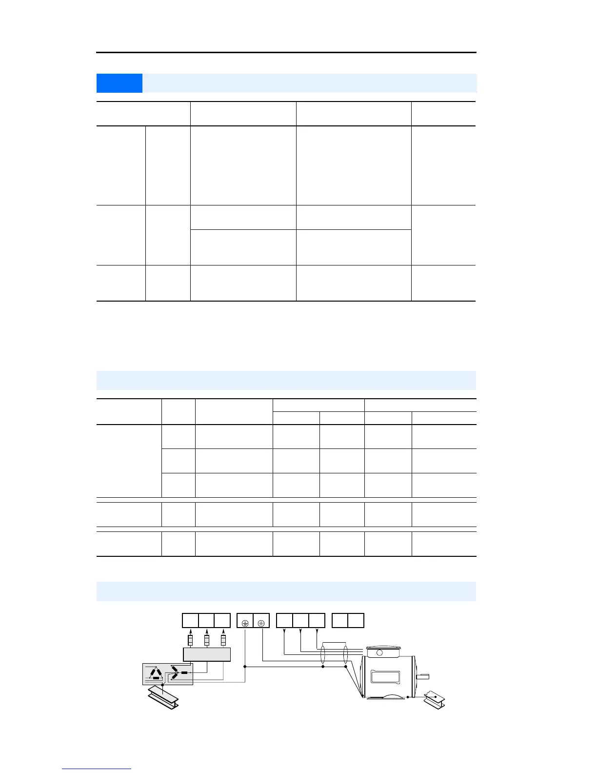
Power & Ground Wiring
PE
L1
R
L2
S
L3
T
T1
U
T2
V
T3
W
PE
+DC BRK
Required
Input Fusing
Required Branch
Circuit Disconnect

 Loading...


