English-8 PowerFlex 70 Adjustable Frequency AC Drive Quick Start
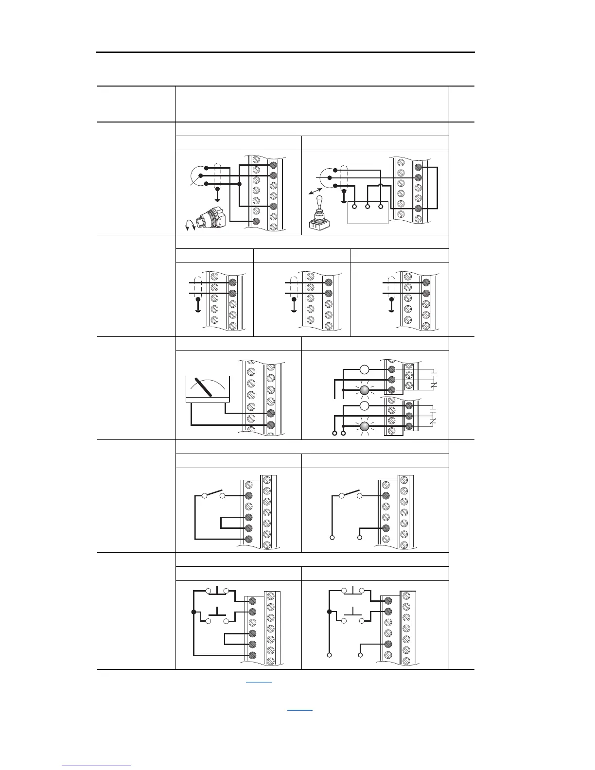
I/O Wiring Examples
Input/Output Connection Example
(3)
Related
Param.
Potentiometer
(1)
10k Ohm Pot.
Recommended
(2k Ohm minimum)
Joystick
(1)
±10V Input -
100k ohm input
impedance
[Speed Ref A Sel] = “Analog In 1” 090
to
095
320
to
327
361
to
366
Potentiometer Joystick
Analog Input
Bipolar:
±10V
Unipolar:
0 to +10V, 100k
ohm impedance
4-20 mA, 100 ohm
impedance
[Speed Ref A Sel] = “Analog In 2”
Bipolar
(1)
Unipolar (Voltage) Unipolar (Current)
Analog/Digital
Output
0 to +10V Output -
Can drive a 2k
Ohm load (25 mA
short circuit current
limit)
Analog Output Digital N.O. / N.C. Output 341
to
344
380
to
387
2 Wire Control
(2)
-
Non-Reversing
Requires 2-wire
functions only
([Digital In1 Sel]).
Using 3-wire selec-
tions will cause a
type 2 alarm.
24V DC Input
(4)
: [Digital In2 Sel] = “Run” 361
to
366
Internal Supply External Supply
3 Wire Control
Requires 3-wire
functions only
([Digital In1 Sel]).
Using 2-wire selec-
tions will cause a
type 2 alarm.
24V DC Input
(4)
: [Digital In1 Sel] = “Stop – CF”, [Digital In2 Sel] = “Start”
Internal Supply External Supply
(1)
Refer to the Attention statement on page 2 for important bipolar wiring information.
(2)
Important: Programming inputs for 2 wire control deactivates all HIM Start buttons.
(3)
Examples show hardware wiring only. Refer to page 7 for parameters that must be adjusted.
(4)
If desired, a User Supplied 24V DC power source can be used. Refer to the “External” example.
14
15
22
10
18
19
22
Com
Power Source
-10V +10V
18
19
–
+
18
19
Common
+
20
21
Common
+
+–
22
23
11
12
13
24
25
26
Power
Source
or
2
7
8
9
Stop-Run
+24V Common
2
8
Stop-Run
1
2
7
8
9
Stop
Start
+24V Common
1
2
8
Stop
Start

 Loading...


