PowerFlex 70 Adjustable Frequency AC Drive Quick Start English-9
❏ 1. Verify input supply voltage.
❏ 2. Check output wiring.
❏ 3. Check control wiring.
❏ 4. Apply AC power and control voltages to the drive.
If any of the six digital inputs are configured to Stop – CF
(CF = Clear Fault) or Enable, verify that signals are present or the
drive will not start. Refer to Troubleshooting – Abbreviated Fault &
Alarm Listing on page 16 for a list of potential digital input conflicts.
If the STS LED is not flashing green at this point, refer to Status
Indicators on page 9.
❏ 5. Select Start-Up method: SMART Start or Assisted Start-Up.
Step 4 Start-Up Check List
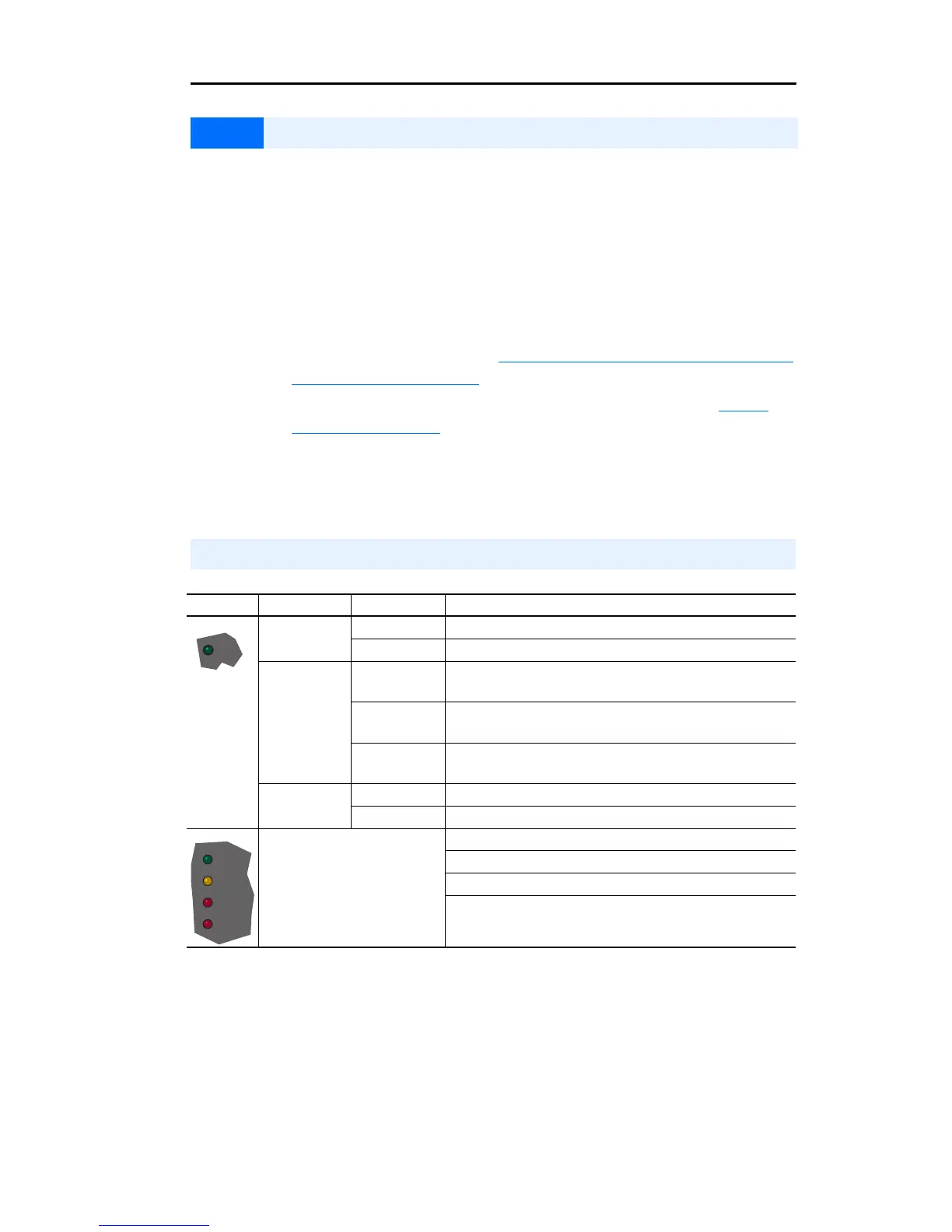
Status Indicators
Name Color State Description
Green Flashing Drive ready, but not running and no faults are present.
Steady Drive running, no faults are present.
Yellow Flashing,
Drive Stopped
An inhibit condition exists, the drive cannot be started.
Check parameter 214 [Start Inhibits].
Flashing,
Drive Running
An intermittent type 1 alarm condition is occurring.
Check parameter 211 [Drive Alarm 1].
Steady,
Drive Running
A continuous type 1 alarm condition exists.
Check parameter 211 [Drive Alarm 1].
Red Flashing A fault has occurred.
Steady A non-resettable fault has occurred.
Refer to the Communication
Adapter User Manual.
Status of DPI port internal communications (if present).
Status of communications module (when installed).
Status of network (if connected).
Status of secondary network (if connected).
STS
PORT
MOD
NET A
NET B

 Loading...


