24 Rockwell Automation Publication 750-RM003A-EN-P - April 2018
Chapter 1 Selection Considerations
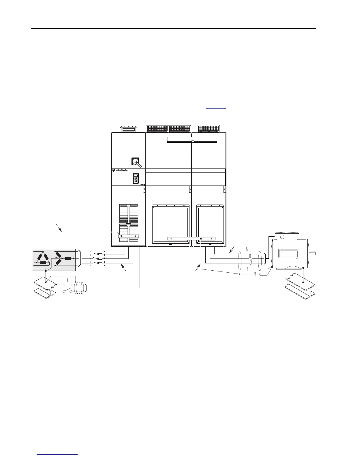
Recommended Grounding Scheme
If the bus supply is installed within an enclosure, use a single safety ground
point or ground bus bar connected directly to building steel. All circuits
(including the AC input ground conductor) must be grounded independently
and directly to this point or ground bus bar. A suitable jumper conductor
should be installed between the bus supply and common bus inverter PE
ground bus bars. We recommend a wye secondary isolation transformer with
solid grounded X0 connection (Figure 1
).
Figure 1 - Recommended Grounding Method
Bus Capacitance and
Precharging Consideration
The PowerFlex 700AFE bus supply had limitations on the maximum DC bus
capacitance that could be connected.
The PowerFlex 755TM bus supply has similar requirements for maximum
connected DC bus capacitance. The precharge circuits are not designed to
charge DC bus capacitance greater than the maximum indicated. If the existing
external DC bus capacitance is greater than the maximum for the selected bus
supply, it may be necessary to select a larger rating for the PowerFlex 755TM
bus supply.
DC+
DC-
DC+
DC-
PE PE
PEPE
R (L1)
S (L2)
T (L3)
U (T1)
V (T2)
W (T3)
SHLD
To Line PE (Input Bay)
To PE (Power Bay)
Input Bay Power Bay

 Loading...


