64 Rockwell Automation Publication 750-RM003A-EN-P - April 2018
Chapter 1 Selection Considerations
Control Terminal Comparison
This section compares the control terminal blocks of the PowerFlex 700AFE
and PowerFlex 755TM bus supplies.
PowerFlex 700AFE Digital and Analog I/O
Inputs and outputs on the PowerFlex 700AFE converter are mostly predefined
factory defaults that interface with the standard door-mounted operator
control devices. Standard default I/O descriptions are shown Table 31
.
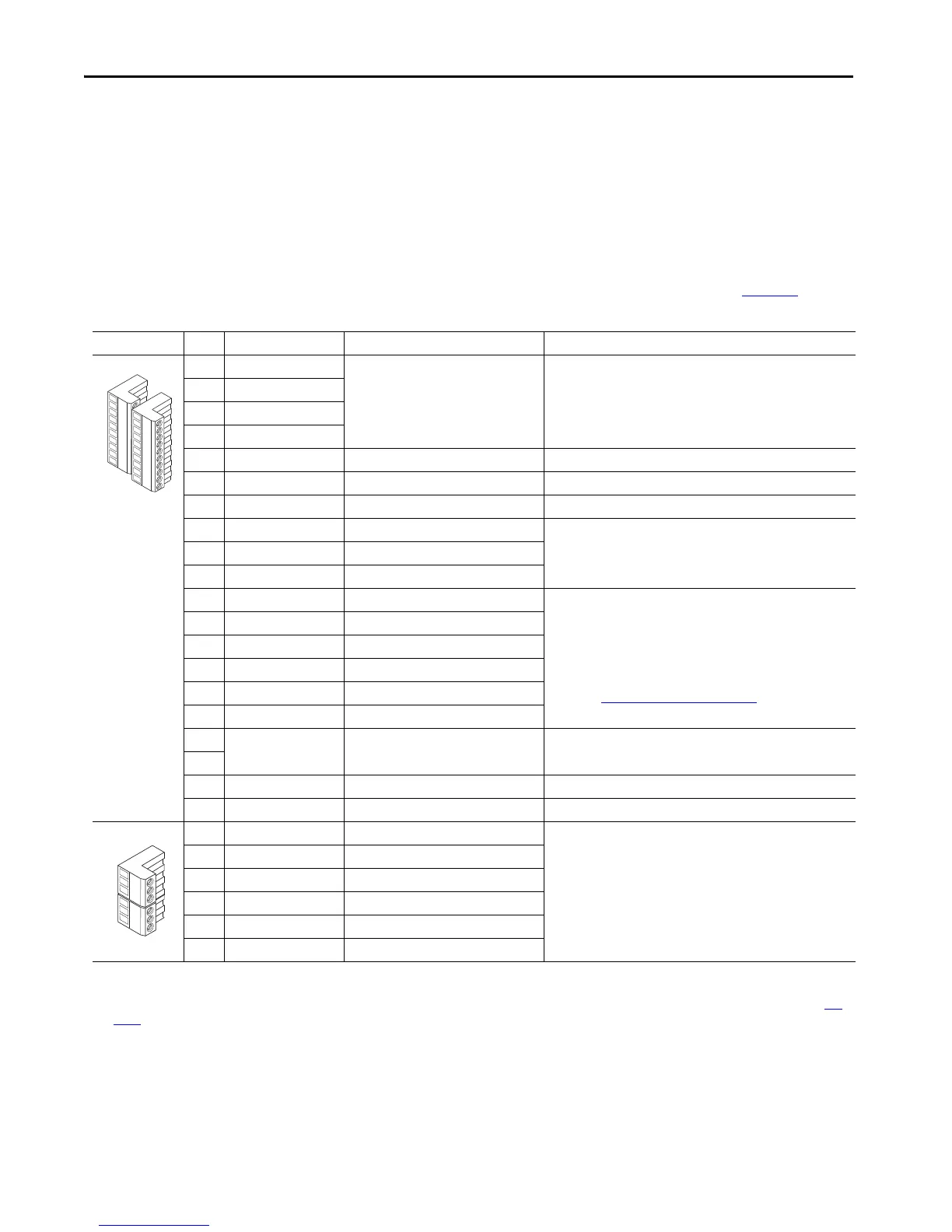
Table 31 - PowerFlex 700AFE Control Terminals
No. Signal Factory Default
(1)
Description
1 Analog In 1 (–)
(2)
Depends on parameter settings Isolated
(3)
, bipolar, differential, 9-bit & sign, 88 kΩ input impedance.
A jumper selects 0…10V, ±10V, or 4-20 mA.
Default: 0…10V (Ri = 200 kΩ), 4-20 mA (Ri = 100 Ω).
2 Analog In 1 (+)
(2)
3 Analog In 2 (–)
(2)
4 Analog In 2 (+)
(2)
5 –10V Pot Reference — 2 kΩ min, 10 mA max load, 1% accuracy
6 Pot Common (GND) — For (+) and (–) 10V pot references
7 +10V Pot Reference — 2 kΩ min, 10 mA max load, 1% accuracy
8 Analog Out 1 (+)
(2)
Depends on parameter settings Bipolar (current out is not bipolar), 9-bit and sign, 2 kΩ min load.
A jumper selects 0…10V, ±10V, or 4-20 mA.
9 Analog Out Common —
10 Analog Out 2 (+)
(2)
Depends on parameter settings
11 Digital In 1 RunCmd 24V DC - Opto isolated (250V)
Low State: less than 5V DC
High State: greater than 20V DC, 11.2 mA DC
On-Time: < 16.7 ms, Off-Time < 1 ms
Hardware ENABLE: Digital In 6 is jumper selectable for Hardware
Enable. See Hardware Enable Circuits
on page 55.
12 Digital In 2 Ext. Reset
13 Digital In 3 Enable Mcont
14 Digital In 4 Contactor Ack
15 Digital In 5 LCL Temp
16 Digital In 6 Depends on parameter and jumper settings
17 Digital In Common — Allows source or sink operation.
18
19 +24V DC
(4)
— +24V DC internal power supply output.
20 24V Common
(4)
— Common for internal 24V DC power supply.
21 Digital Out 1 – N.C.
(5)
Contact Ctrl Max. resistive load:
240V AC/30V DC – 1200VA, 150 W
Max. current: 5A, min. load: 10 mA
Max. inductive load:
20V AC/30V DC – 840VA, 105 W
Max. current: 3.5A, min. load: 10 mA
22 Digital Out 1 Common —
23 Digital Out 1 – N.O.
(5)
Contact Ctrl
24 Digital Out 2 – N.C.
(5)
Fault
25 Digital Out 2/3 Com. —
26 Digital Out 3 – N.O.
(5)(6)
Active
(1) Important: Digital Inputs 1, 3, 4, and 5, and Digital Outputs 1 and 2 are factory-wired and programmed to operate from the controls on the front of the enclosure. Digital Output 3 is programmable
and factory-wired for +24V DC only. Do not change the wiring and programming for those digital inputs and outputs, or it results in malfunction of the system.
(2) Important: Input must be configured with a jumper. AFE damage can occur if jumper is not installed properly. See Analog I/O Configuration in PowerFlex 700AFE User Manual, publication 20Y-
UM001.
(3) Differential Isolation - External source must be maintained at less than 160V regarding PE. Input provides high common mode immunity.
(4) 150 mA maximum load. Can be used to provide control power from an external 24V source when main power is not applied.
(5) Contacts in an unpowered state. Any relay that is programmed as Fault or Alarm energizes (pick up) when power is applied to the AFE, and de-energizes (drop out) when a fault or alarm exists.
Relays selected for other functions energize only when that condition exists and de-energizes when the condition is removed.
(6) When this output is configured as active, it can be wired to the Enable input of the connected drives to prevent the AFE from supplying power when the AFE is inactive.

 Loading...


