90 Rockwell Automation Publication 750-RM003A-EN-P - April 2018
Appendix A Enclosure Information
Cooling and Airflow
Comparison
This section describes cooling and airflow requirements for the PowerFlex
700AFE and PowerFlex 755TM bus supplies. Compare the requirements for
the existing bus supply to the equivalent PowerFlex 755TM bus supply to
confirm the location can support the requirements of the migration solution.
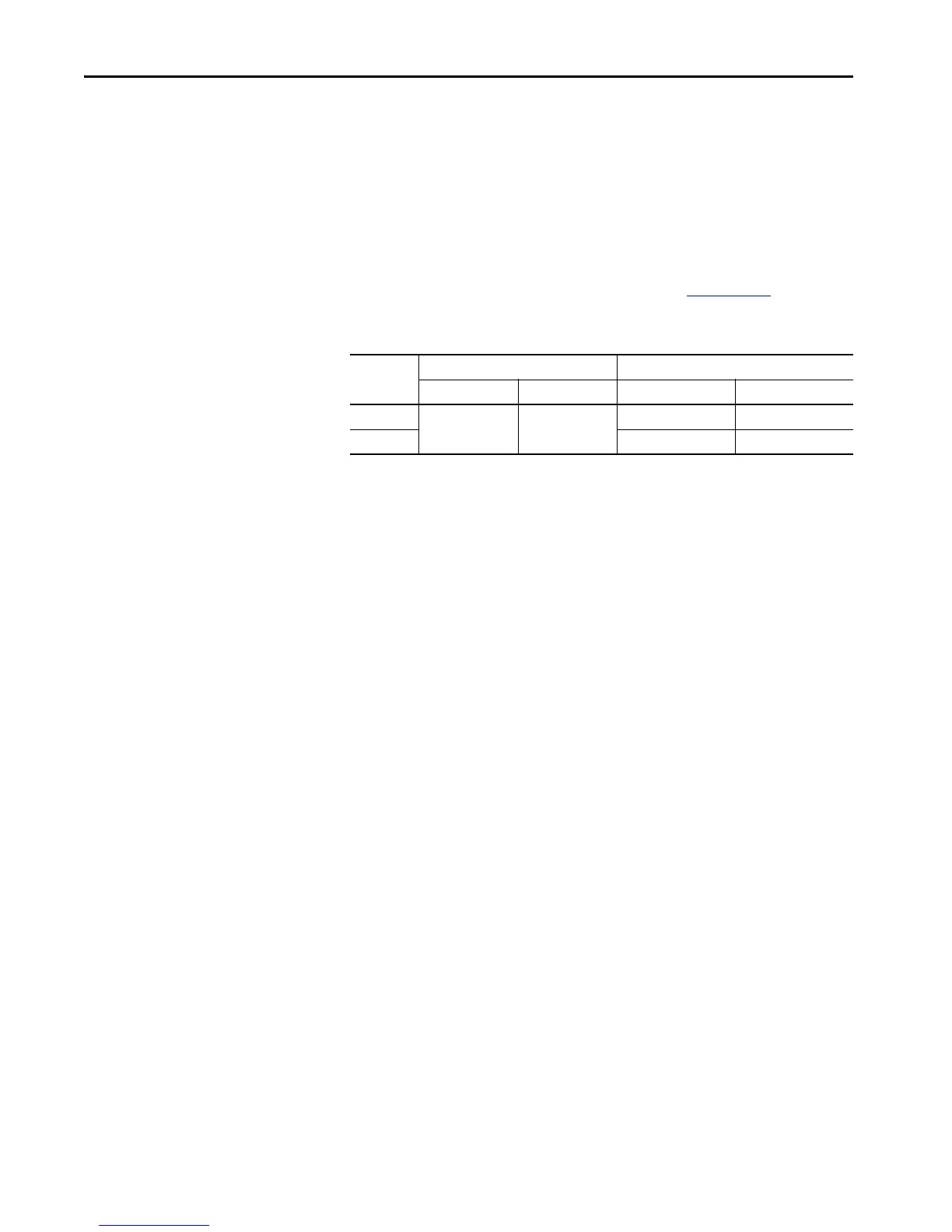
PowerFlex 700AFE Installation Requirements
See the PowerFlex 700AFE user manual, publication 20Y-UM001, for detailed
environmental specifications for frame 10 and 13 bus supplies.
Table 42 - Environmental Specifications
Frame Size Surrounding Air Temperature
(2)
(2) For a PowerFlex 700AFE in the IP20 2500 MCC Style enclosure, this air means surrounding the outside of the enclosure.
Minimum Airflow
Normal Duty Heavy Duty Power Module LCL Filter
10
0…40 °C
(32…104 °F)
0…40 °C
(32…104 °F)
1400 m
3
/hr (824 cfm) 1100 m
3
/hr (647 cfm)
13
(1)
(1) The frame 13 690V noncondensing AFE has only normal duty operation at nominal rated power and maximum ambient
temperature at 35 °C (95 °F).
4200 m
3
/hr (2472 cfm) 1300 m
3
/hr (765 cfm)

 Loading...


